Results 1 to 14 of 14

Thread: My Easter weekend brake rebuild - rust, rust, rust, DOT 4 in the face and more rust..

  1. #1
    HEXUS.Metal Knoxville's Avatar
    Join Date
    Jul 2003
    Location
    Down In A Hole
    Posts
    9,388
    Thanks
    484
    Thanked
    442 times in 255 posts
    • Knoxville's system
      • Motherboard:
      • Intel X58
      • CPU:
      • Intel i7 920
      • Memory:
      • 2GB DDR3
      • Storage:
      • 1TB
      • Graphics card(s):
      • ATi HD3450
      • PSU:
      • Generic
      • Case:
      • Cheap and nasty
      • Operating System:
      • Vista 64
      • Monitor(s):
      • 24" LG LCD
      • Internet:
      • Virgin Media 20mb

    My Easter weekend brake rebuild - rust, rust, rust, DOT 4 in the face and more rust..

    Ahoy-hoy! As some of you may know already, before christmas the entire braking system of my Land Rover, Nero failed spectacularly on my way home one night leaving me with custom brown boxers and a brake pedal suffering from brewers droop. You may also remember the 'orrible looking hunk of rust that I had you all guessing at in a thread I started a little while back - http://forums.hexus.net/automotive/3...play-game.html

    Thankfully the truck now has a completely new dual circuit braking system in place of the old, rotten and generally broken single circuit system that failed on me a few months back and having written up a piece detailing the rebuild for my blog I thought I'd post it up in here for anyone that's interested with a couple of additions/edits.

    So, where do I begin?

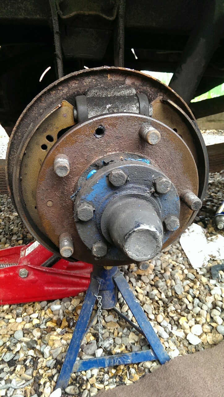
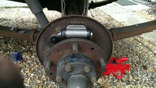
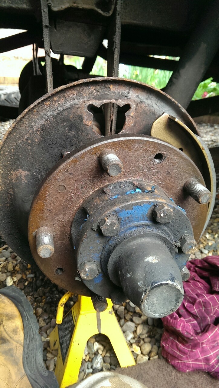
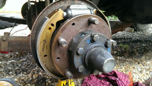
    For those of you that don't know, the original braking system sold as standard on any Landy produced before July 1980 was a single circuit system with 10" drums all round and no servo assistance. As far as stopping distances go by modern standards it is woeful and being single circuit is also prone to complete and total failure in the event that any single component breaks or malfunctions.

    Not good really as I'm sure you can imagine so rather than refit a system I'd never trusted and would certainly never trust again I had two options - Find a front axle from a later vehicle and upgrade the front drums to 11" items as that would enable me to fit the later and arguably the best system, a dual circuit servo assisted system with bigger twin leading shoes in the front, OR fit the system that was available as an optional extra from the late sixties onwards and was standard on LHD exports which is a dual line servo assisted system that uses the existing single leading shoe 10" drums all round.

    There are advantages and disadvantages to both. Twin leading shoes are great for stopping you in forward gears but not so good at stopping you in reverse, plus that system was also fitted to much bigger, heavier long wheel base models so the extra stopping power would be even more noticeable in a lighter vehicle. Single leading shoe systems don't provide as much stopping power in forward gears because the trailing shoe simply cannot exert as much force on the drum as the leading shoe, it is however arguably a better balance for a short wheel base vehicle and simpler to retrofit these days because as I discovered to my peril a later front axle is now a nightmare to track down. Damn government scrappage scheme.... Anyway, in the end I opted for the simpler upgrade of the two purely because of the parts availability.

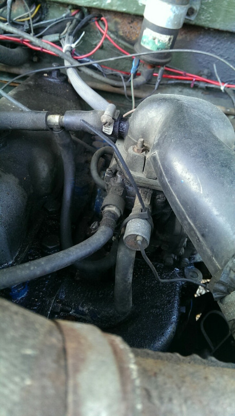
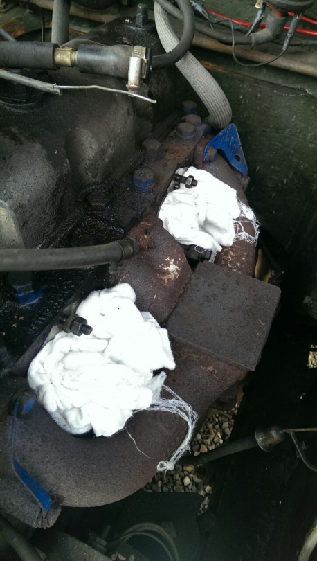
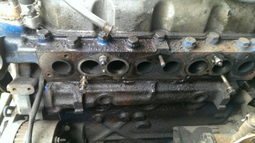
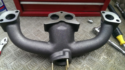
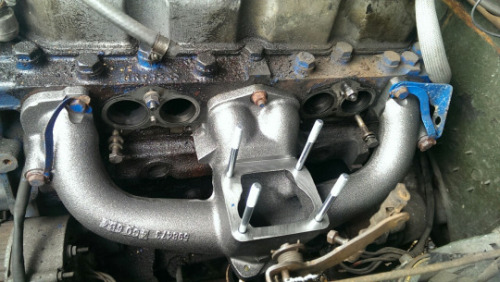
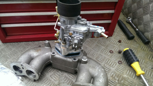
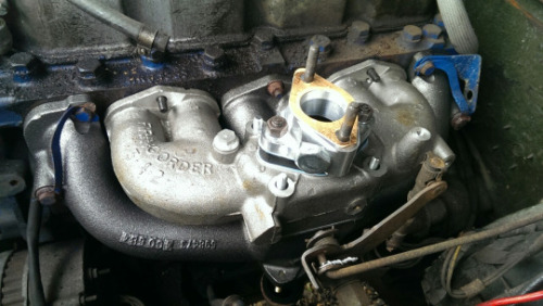
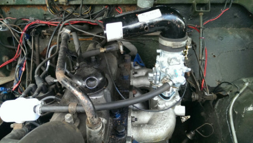
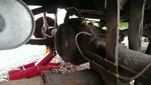
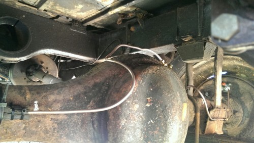
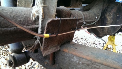
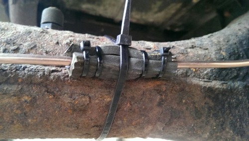
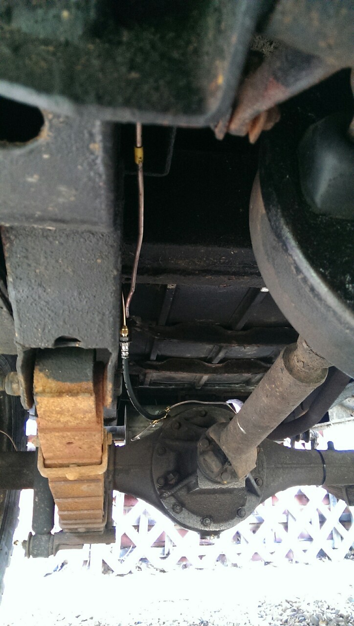
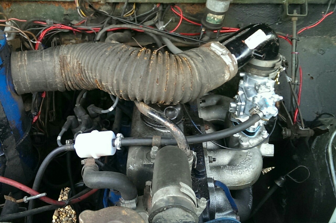
    This meant I had to upgrade my inlet/exhaust manifold so that I could pull a vacuum for the servo from the engine rather than fitting a pump. Although in fairness given the number of new parts I had to scrounge together to do it a pump may well have been simpler. Let’s not think about that though, besides, vacuum pumps are for dirty dirty diesels and anything you run off the front of an engine will steal power, even if it is only a little bit.

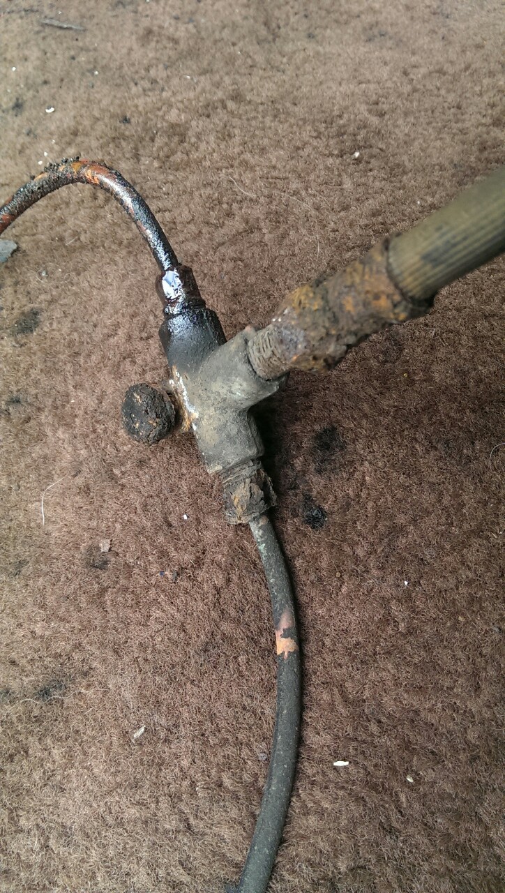
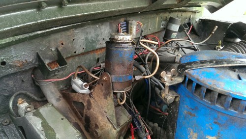
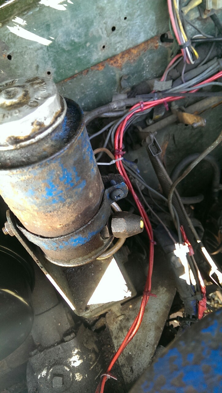
    First of all the old bean can brake and clutch resevoir had to be relocated as in its original location it would be right in the way when fitting the new master cylinder and servo. The new brake master cylinder runs off its own resevoir anyway so the can will only be serving fluid to the clutch hydraulics from here on out anyway. I flipped it around on the bracket, carefully bending the pipework so as to not put strain on the connections -


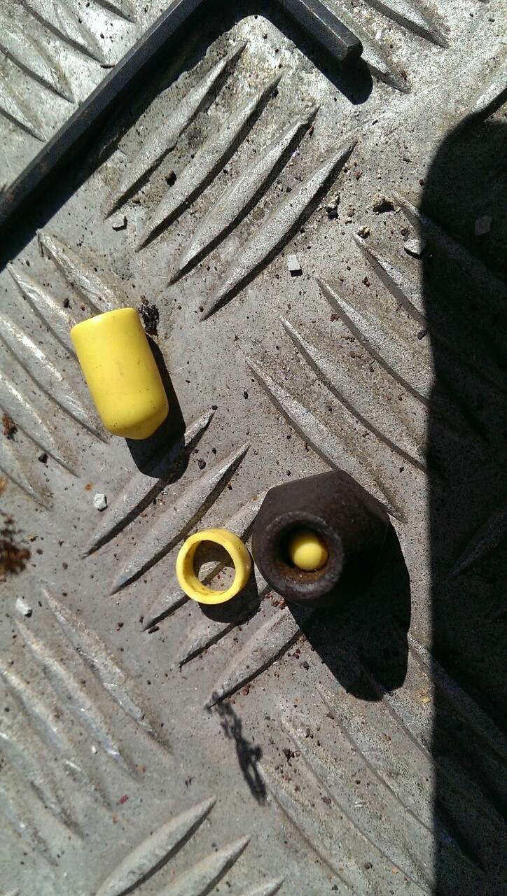
    As you can see I spilled a little fluid out of the top of the can but nothing that couldn’t be topped up. I then removed the brake master outlet pipe and used the connector and a rubber bung from my brake line kit to fashion a stopper. There’ll be no fluid in the brake resevoir within the can but just in case I miss and get some in there when topping up the clutch fluid in future it shouldn’t go anywhere I don’t want it to. Which is good, because DOT 3/4 isn’t exactly pleasant stuff -


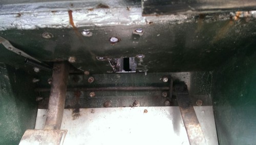
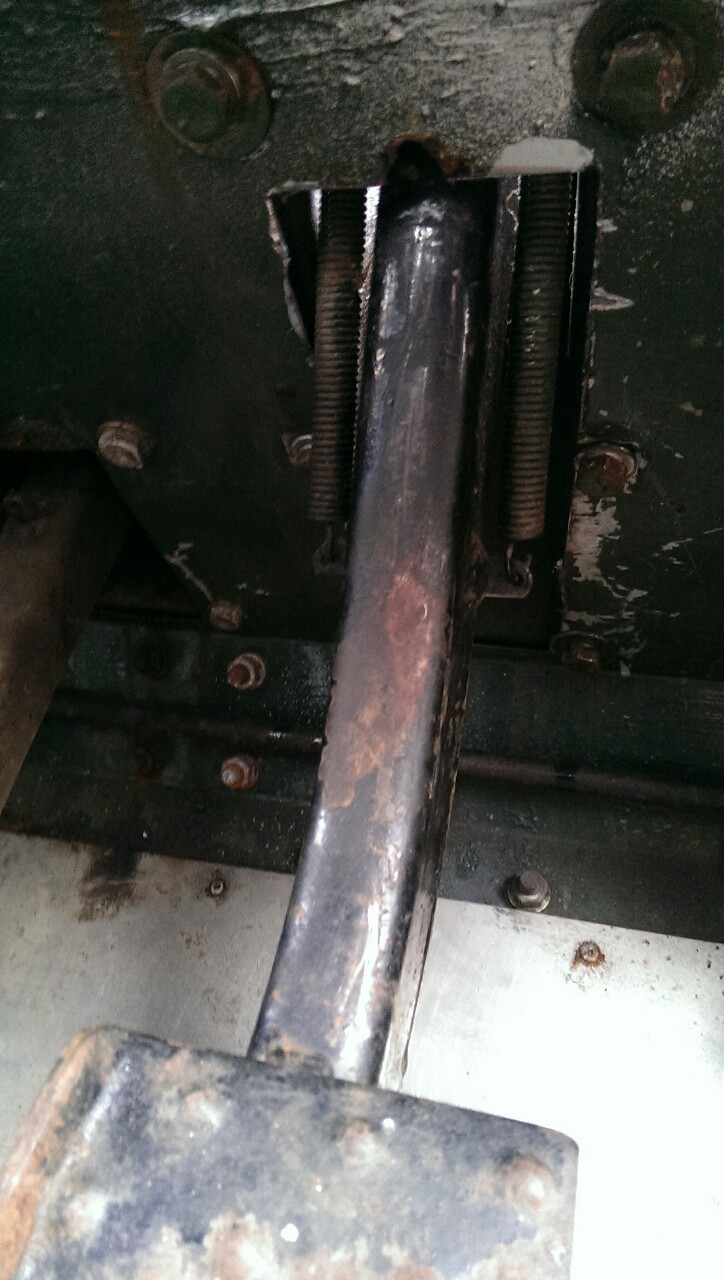
    With what is now the clutch resevoir relocated I could turn my attention to removing the old pedal box. Six studs and a couple of spade connectors later and my pedal box was much more *ahem*well ventilated -


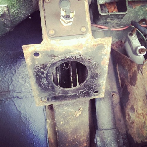
    I then cut out a bigger aperture for the new pedal as it needs a lot more travel than the old one and has return springs on both sides. I used the point where the wires run through the firewall to the original brake light switch as a rough guide that’s about right for the new pedal length ways and then I just needed to widen the gap slightly so the return springs don’t foul on either side of the hole. -


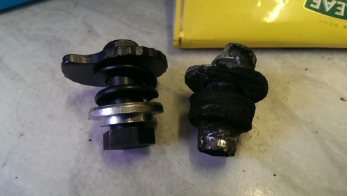
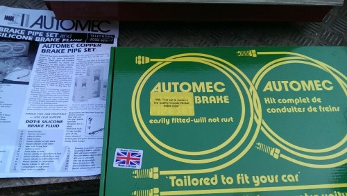
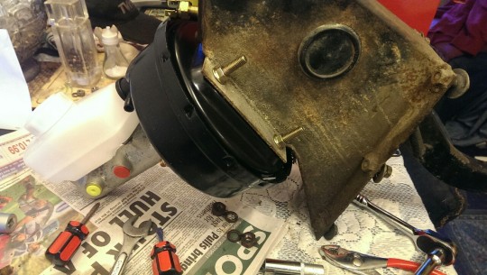
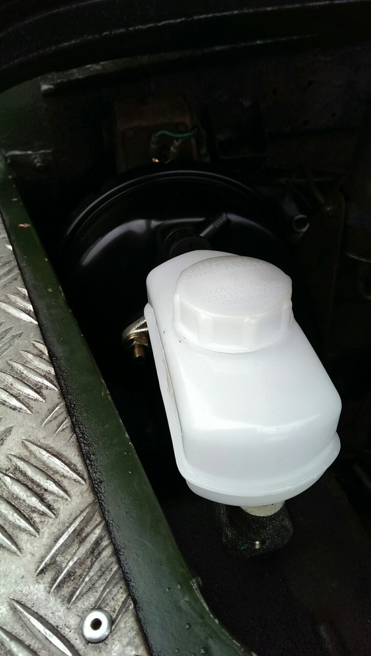
    With that done and the new pedal assembly bolted firmly into place I could then go about fitting the brand new servo and master cylinder from Paddocks Spares. I'd already test fitted the new parts to my junk on the dining room table and fitted a new brake light switch in the process. No, I wasn't popular...


    So knowing that everything would fit together nicely I just had to be careful not to work the master cylinder while dry as doing so would ruin it very quickly -


    Thankfully the drivers side wing on my vehicle has the optional cut out for this system already but in other/older Series Land Rovers that would have needed trimming back as well for clearance. All in all it took around four to five hours to complete this part of the job. There were some fiddly bits to contend with such as the connection between the pedal and the servo unit, which needs a split pin inserted either somewhere you can’t get your hands without the bonnet off or requires you to telepathically fit it on the side of the pedal assembly you can’t see by reaching over from the drivers side of or front of the vehicle. It was worth taking my time enlarging the aperture a bit at a time as well - You can cut it all off in one go but it’s a lot harder to stick it back on again!

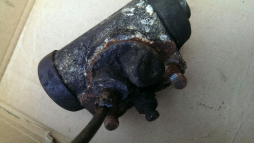
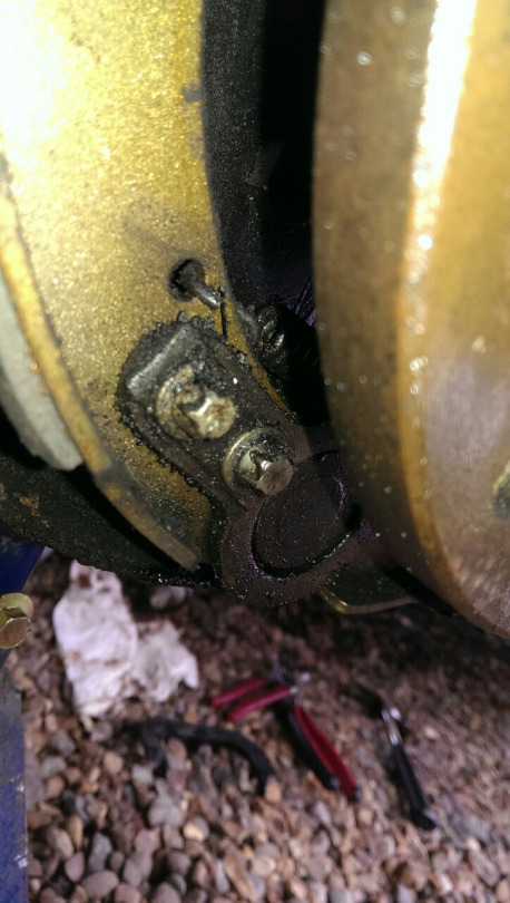
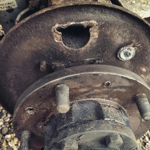
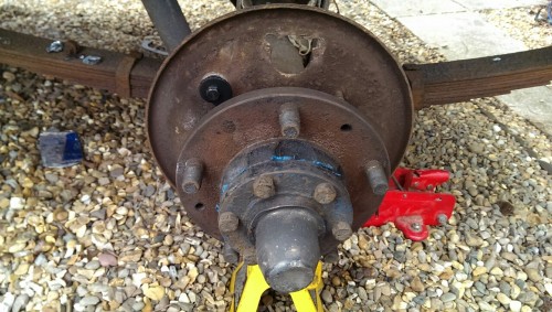
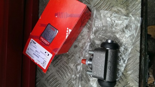
    Other than that though, and the huge amount of silicone sealer a previous owner had put between the old pedal assembly and the bulkhead gacking the bolts slightly on their way out it was a fairly simple job and I decided to call it a day there and think about the next stage of the job - changing the inlet manifold for one tapped for a vacuum line and fitting a carburretor to suit, before stripping out the old wheel cylinders, shoes and then plumbing everything together.

    I’ll split the posts up here, because otherwise this will become a massive post and that might infringe on Saracens trademark Megaposts

    Plus lifting and editing sections outta the blog the way I intend to it's just easier for me to keep track of what goes where and how. I'm currently writing up part two so hopefully it won't be too long until you get to see some really 'orrible rusty bits
    Last edited by Knoxville; 11-04-2015 at 03:45 PM. Reason: broken images

  2. Received thanks from:

    peterb (11-04-2015),Tumble (11-04-2015)

  3. #2
    The late but legendary peterb - Onward and Upward peterb's Avatar
    Join Date
    Aug 2005
    Location
    Looking down & checking on swearing
    Posts
    19,378
    Thanks
    2,892
    Thanked
    3,403 times in 2,693 posts

    Re: My Easter weekend brake rebuild - rust, rust, rust, DOT 4 in the face and more ru

    Looking forward to the next instalment of Project Landy!
    (\__/)
    (='.'=)
    (")_(")

    Been helped or just 'Like' a post? Use the Thanks button!
    My broadband speed - 750 Meganibbles/minute

  4. #3
    HEXUS.Metal Knoxville's Avatar
    Join Date
    Jul 2003
    Location
    Down In A Hole
    Posts
    9,388
    Thanks
    484
    Thanked
    442 times in 255 posts
    • Knoxville's system
      • Motherboard:
      • Intel X58
      • CPU:
      • Intel i7 920
      • Memory:
      • 2GB DDR3
      • Storage:
      • 1TB
      • Graphics card(s):
      • ATi HD3450
      • PSU:
      • Generic
      • Case:
      • Cheap and nasty
      • Operating System:
      • Vista 64
      • Monitor(s):
      • 24" LG LCD
      • Internet:
      • Virgin Media 20mb

    Re: My Easter weekend brake rebuild - rust, rust, rust, DOT 4 in the face and more ru

    Cheers fella, I'm hoping to rewrite the next section later tonight and post the next installment tomorrow. Folks on my blog have sort of had the updates as they've happened which isn't necessarily a build order that would make sense to the uninitiated. I'm also going to try adding a little more exposition and context here as I'm aware not everyone that will stumble across this will know anything about Landys whereas most of my followers there are already owners

  5. #4
    Beard hat ftw! steve threlfall's Avatar
    Join Date
    Jul 2003
    Location
    West Midlands
    Posts
    6,745
    Thanks
    302
    Thanked
    195 times in 124 posts
    • steve threlfall's system
      • Motherboard:
      • Gigabyte Z77-D3H
      • CPU:
      • Core i5-3570K
      • Memory:
      • 8GB Corsair Vengeance DDR3
      • Storage:
      • Samsung 830 256
      • Graphics card(s):
      • Radeon HD6870
      • PSU:
      • Corsair HX750
      • Case:
      • Antec P280
      • Operating System:
      • Windows 7 Home Premium 64bit
      • Monitor(s):
      • Dell 2407 WFP 24" Widescreen, Rev A04
      • Internet:
      • Virgin 120/12 mb

    Re: My Easter weekend brake rebuild - rust, rust, rust, DOT 4 in the face and more ru

    Mightily impressive Knox

    I won't pretend that I understand much (any) of it, but this is fantastic work all the same. You've no doubt enhanced an already awesome vehicle. I don't know if you caught the last TG Landy feature, but if Hammond catches a glimpse of this, you'll be getting a call to pop over and give him a hand with his.

  6. #5
    HEXUS.Metal Knoxville's Avatar
    Join Date
    Jul 2003
    Location
    Down In A Hole
    Posts
    9,388
    Thanks
    484
    Thanked
    442 times in 255 posts
    • Knoxville's system
      • Motherboard:
      • Intel X58
      • CPU:
      • Intel i7 920
      • Memory:
      • 2GB DDR3
      • Storage:
      • 1TB
      • Graphics card(s):
      • ATi HD3450
      • PSU:
      • Generic
      • Case:
      • Cheap and nasty
      • Operating System:
      • Vista 64
      • Monitor(s):
      • 24" LG LCD
      • Internet:
      • Virgin Media 20mb

    Re: My Easter weekend brake rebuild - rust, rust, rust, DOT 4 in the face and more ru

    Cheers bud, much appreciated! Although Hammonds basket case of a Series 1 is too nice for me to be playing with. That's £50k's worth of classic car on todays market if done right and I'm well known in Land Rover circles for wanting to do bad things to Series 1's and MB Willys Jeeps... I'd channel the chassis, put a small block LS Chevrolet engine in one, stick it on road tyres, use it to scare boy racers and drop the value by about £45k

    As far as not understanding anything I shall try and elaborate.... Bear with though, I'm only on my first cuppa of the day

    Your Swift, aside from all its ABS related tom foolery which I can't claim to fully understand has a system that operates under similar principles to the one I've fitted. You've got the servo, which on yours is tucked up behind the master cylinder on the drivers side. It uses a vacuum stolen from somewhere in the engine or an electrically/belt driven pump to mulitply the amount of force you put into the brake master cylinder when you push down on the pedal. Basically if you disconnected your servo you'd be in for leg day at the gym every time you hit the brakes if you wanted to pull to a stop in the same distance you can with one fitted.

    The easiest way to describe your and my new master cylinder is that it's two pistons inside two seperate cylinders fed by a brake fluid resevoir. When you push down on the pedal those two pistons compress the brake fluid, transferring that force all the way through the brake lines to slave cylinders located at the wheels. On a vehicle with disc brakes like yours the slaves are the pistons found in the calipers that push the pads into the discs, you could have 2/4/8/12 of them per caliper depending on the car, the more you add the greater the stopping power in theory. Although there are other variables.

    In my case, having drum brakes the slaves are wheel cylinders with two pistons that push the brake shoes mounted on either side outwards into the drum. I waffled on about wanting to fit twin leading shoes on the front axle. It sounds clever but all it really means is that the pistons in the wheel cylinders are located and operate in such a fashion that both brake shoes in the drum act as leading shoes when you try and stop the vehicle going forwards. All the term leading shoe means is that when the shoe hits the rotating surface inside the drum the drums rotation actually helps the shoe dig into the surface of the drum. A trailing shoe is completely reliant on the wheel cylinder to push it into the surface of the drum and is a little less efficient as a result.

    Previously, my master cylinder had one piston inside one cylinder operating all four slaves and doing all of the work. So if anything in the system failed (as mine did), say a slave goes or theres a hole in the brake lines, anything like that, suddenly you lose all your fluid and as such all braking ability. With systems like yours and my new system if a component in the rear brakes dies, you lose rear brakes but still have the fronts and vice versa. It's like wiring an electrical system in parralel instead of series. Most countries actually require dual circuit brake systems to be fitted to vehicles by law for safety reasons. My vehicle was built before such laws applied so it's not essential if I just want the truck road legal but it's a damn good idea for the sake of safety!

    Hopefully I haven't got too much of that explanation back to front, I'm sure someone will tell me if I have. It should all make a bit more sense hopefully when I put up some pictures of the innards of my brake drums


    Anyway.... Where was I?

    Yes, inlet manifolds and things.

    This job actually got carried out the weekend before because I knew I had all the parts to make everything work. It's not a build order that would have made sense here though. Plus, you guys were introduced to the rebuild sort of via the piece of junk I posted in my first thread so I figured going through how that was fitted would be a better place to start.

    So, I've got a dual line master cylinder and a servo, but I needed somewhere to get a vacuum line from for the servo to use. The easiest place to do that with a petrol engine is to tap into the vacuum generated naturally by the engine inside the inlet manifold.

    I only had one problem, this horrible thing -


    I’m not sure exactly what kind of Weber it is, my first guess was perhaps a 32/36 but it doesn’t look right, I’m open to suggestion if anybody knows because I’ve yet to pull it apart. It definitely wasn’t fitted correctly at any rate and it was leaking fuel all over the top of the equally non-standard inlet manifold which didn't have the tapped thread I'd need to steal a vacuum. I gathered up one NOS Series 3 lightweight inlet manifold, a Weber 34 ICH carburettor and a conversion block, a horde of gaskets, connector hoses, phelonic blocks and a collection of studs to top it all off. I removed the whole shebang and…


    ....my inlets was cleary full of baby white rabbits. With cotton tail and his friends in there, how was it ever going to run??!!

    No, I discovered that to fit that inlet manifold whoever had done it had also welded a dirty great plate over the top of the exhaust manifold. Why? DOn't know, don't care. Long story short, it went, which left the engine looking a little lonely -


    Until some new bits arrived -


    From then on it actually wasn’t too difficult to put everything back together again as by some miracle I had actually ordered everything I needed. Something I never before thought possible.

    The new exhaust manifold went on. I’ve read different reports on whether or not you’re supposed to fit this using a gasket or not, depending on what version of the 2.25 petrol engine you have. In my case there were two steel gaskets fitted to the inlet and nothing on the exhaust so I left the big paper gasket in the box and reassmbled things the same way -


    Those big shiny inlet to exhaust manifold studs are going to have to come back out in a minute but I’ll figure that out later. In the meantime I’d put together the inlet manifold, carb and adaptor plate one evening so that it was ready to bolt on -


    That too had to come apart to get everything together later on but you’ll see why and how in a second. The other thing I had to take into account was that the Weber 34 ICH I’d purchased needs a different action to operate it from the throttle rod. Solex carburretors, along with the Weber that had been previously fitted need the throttle linkage to push up on the arm when you push down on the pedal. Zenith and Weber 34′s need the opposite. they need the linkage to pull down on them when you step on the gas. So that was next and that was actually the only thing I couldn’t scrounge up parts for without taking my parts ordering pyschosis stateside and ordering in from the U.S. Some incredibly helpful person on AU-lro’s forum had however posted a link to somebody that had flipped the bell crank for a Solex upside down and made it suit a Weber. After a bit of headscratching, looking at it, thinking about it and playing with the return spring I managed to do the same -


    Note - The completely not hacked piece of galvanised wire acting as a throttle rod end clip until the proper job arrives.

    Next it was inlet manifold on. This is where I learned all my lessons about order of assembly. Inlet to exhaust gasket, then inlet manifold, then put the studs in to join the two in glorious matrimony and finally take the carburettor back off the adaptor block so you can actually get to tighten everything up again.


    Bolt that lot back together and voila! All done, except for the intake hose and ar filter anyway. Which is lurking somewhere out of shot. Planning something devious no doubt...


    By the time that was all done, sunset was about thirty minutes off and I needed beer and meat to satisfy my various desires so I jacked up the idle speed adjustment, dialed in a vague mixture and tried the key. It fired up not long after the fuel hit the filter which was promising and it very much wanted to run. I lost a day the day after to rain and generally British weather but a couple of mornings later I managed to spend an hour tuning it up a bit more and she idles nicely. The final thing to do will be to find a kind individual with a Co2 gun and fine tune her that last little bit
    Last edited by Knoxville; 12-04-2015 at 03:25 PM.

  7. Received thanks from:

    steve threlfall (12-04-2015)

  8. #6
    HEXUS.Metal Knoxville's Avatar
    Join Date
    Jul 2003
    Location
    Down In A Hole
    Posts
    9,388
    Thanks
    484
    Thanked
    442 times in 255 posts
    • Knoxville's system
      • Motherboard:
      • Intel X58
      • CPU:
      • Intel i7 920
      • Memory:
      • 2GB DDR3
      • Storage:
      • 1TB
      • Graphics card(s):
      • ATi HD3450
      • PSU:
      • Generic
      • Case:
      • Cheap and nasty
      • Operating System:
      • Vista 64
      • Monitor(s):
      • 24" LG LCD
      • Internet:
      • Virgin Media 20mb

    Re: My Easter weekend brake rebuild - rust, rust, rust, DOT 4 in the face and more ru

    Now I had a servo, and I'd bolted the right bits onto the engine to help it work I could work on the brakes themselves next. Which meant stripping out all the old copper lines, hoses, wheel cylinders and shoes so it was wheels and drums off and inspection time -


    Thankfully I’d ordered some new hub screws, not because they were seized or had the heads chewed off them but simply because there weren’t any on either side of the rear axle. Anyway, as you can see, once I'd got the drums off I could tell the shoes weren’t actually that badly worn, so those have been bagged, boxed and packed away for possible future applications.

    This is also the ideal picture to point at if I want to try and explain leading shoes and trailing shoes... You should be able to see just from looking at the picture. As the piston in the wheel cylinder pushes the shoe on the right into a drum that's rotating clockwise around it that clockwise rotation will actually help the shoe dig in. The one on the left will just drag along the surface because the drum is rotating away from the surface of the shoe, not into it. Unless I'm stopping in reverse, in which case the opposite applies.

    Anywhoo, back to the job at hand... The springs and wheel cylinders were pretty ropey, particularly the cylinders which looked as though they’ve been rescued from some sort of deep sea diving expedition -


    How they'd been stopping two tonnes of pig iron and aluminium is beyond me to be honest.

    To get them free I had to remove the retaining plate -


    Then, having made a mental note of which hole the bottom spring uses on both shoes I could then remove the springs, shoes and finally the ropey cylinder from every corner of the vehicle leaving me with a blank canvas -


    What I hadn’t bargained for was the adjusters all of which were seized solidly in place and had to be cut free. Side by side with some quickly sourced replacements you can see just how haggard they really were, what used to be hex heads were now probably the most perfectly rounded part on the vehicle -


    They were also incorrectly assembled (as were mine until I found a rather helpful old document online that detailed the proper assembly order absent from the Haynes manual) on three out of the four back plates, making any adjustment impossible, even if they hadn’t been mauled to death before I’d gotten to them so they all had to be replaced -


    I could then go about reassembling everything with my new components, starting with the cylinders. I chose to use TRW cylinders all round for a variety of reasons. First of all, you don’t skimp on brake components, so that ruled out the kind of cheap and cheerful Chinese made items that you can pick up for less than ten pounds a shot on eBay. Usually I go to Lucas for hydraulic components but availability isn’t quite what it used to be so TRW items seemed a reasonable substitute under the circumstances -


    Nobody online had mentioned having any untoward experiences with them, each one comes with its own three year or 100,000km guarantee and I also happen to know that TRW used to own a rather large and higly reputable local aerospace engineering company, so chances are these are put together by people that know their onions.

    They fitted in place perfectly and the bleed nipple covers are substantial enough and of a high enough quality that I struggled to get them off to bleed the system, so I expect them to hold true for a decent amount of time -


    Once the cylinders were on I could then go about adding the brand new Mintex brake shoes, leading shoe and top spring first, making sure the top spring sat behind the lobe of adjuster -


    I could then add the trailing shoe and bottom spring, being sure to remember which hole had been used to mount the bottom spring in the shoe previously and to check that the shoes would operate in a straight line parralel to the backplate, not at an angle before then finally bolting the retaining plate back into place -


    These Mintex shoes are supposed to be made using a slightly softer compound material providing a better pedal feel than OE spec shoes, I’ll see how they wear over the coming months but I was impressed by the extra studs and plates included with them as well as the comprehensive fitting instructions.

    Having done the same to all four corners I then started removing the old copper brake lines and the flexi hose from the rear axle. Almost every single fixture was seized solid and seeing as it was all to be replaced I elected to save time and simply hacksaw them free. As you can see they were in a pretty sorry state -


    I also found what I presume to be the cause of the initial brake system failure in the length of copper line running to the drivers side wheel cylinder at the same time. I’m not sure if the photograph shows it as well as it would but there was a gash in the line which looked as though somebody had caught the line with a hacksaw blade at some point and no it wasn’t me being over enthusiastic, there was too much oxidisation in and around it for the damage to have been recent. Whoever it was hadn’t cut into the line completely and probably theought they’d get away with it but time, vibration and pressure had worked away at the weakpoint to the point of failure, leaving it so weak that by holding the line below the cut I split it almost clean in half by bending the top part ever so slightly with my finger -


    It was reassuring to find the cause of the problem but seeing as everything was getting changed out for new components anyway it didn’t really change what was to be done next, which was to dig into my Automec copper nickel brake pipe set -


    Automec provide a comprehensive range of ready made kits for almost every Series Land Rover imaginable. I went for their early dual line Series 3 kit because it had imperial fittings, would suit the master cylinder I’d chosen perfectly and would work well with the combination of a Series 3 chassis and Series 2A bodywork with which the trucks been built up. I could have purchased some copper line, a pipe flarer and my own fittings but the investment in decent tools, plus the cost of materials and the time that I’d have to spend making the lines made the full kit a fairly sensible purchase.

    The pipe assembly for the rear axle is relatively simple. Two copper lines run directly out of each wheel cylinder and are supported by brackets situated just above the leaf springs on either side. They then meet at a three way brass junction which is supplied with fluid via a flexi-hose that’s connected to a copper hardline that runs on the inside face of the drivers side chassis rail -


    As you can see the drivers side line is a pretty good fit right out of the box, the passenger side line however seems exceedingly long and if you try to keep bends uniform and to a minimum will sit quite high over the diff. So I had to spend a little bit of time rebending it to fit closer to the diff -


    I used the plastic c-clips provided by Automec to affix the pipe to its supports on both sides and added a couple of cable ties to minimise any movement or vibration as much as possible. For the longer run of pipe on the passenger side I also decided to add a homemade support just to be on the safe side -


    I’m sure there will be some parties that will be absolutely horrified by my use of cable ties but for the most part they have been used in addition to rather than in place of the recommended fixtures and to be completely honest I favour a good strong cable tie over a cheap c or p clip any day of the week. They also have the added bonus of being able to support things in places you cannot easily place an appropriate clip and are easier to replace. So get over it, I already have!

    By this point, having already had to down tools and make a parts run part way through the day I was running a bit low on time and sunlight so finally I ran the copper line down the inside of the chassis rail to feed the rear axle and added the a brand new Britpart flexi-hose to join the two -


    With the back axle buttoned up and done (bar adjustment and bleeding of brakes) and the longest section of pipe on the vehicle fitted I called it a day well spent and put the tools back in the garage. There was still alot more to do though as the front brake lines are notably more complex and there are more clearance issues with steering, bump stops and things of that nature. Hopefully I’ll get that next part of the project up for you guys tomorrow. I haven't even touched on that part on my blog so that should be good

  9. #7
    Studmuffin Flibb's Avatar
    Join Date
    Jul 2003
    Location
    Kent
    Posts
    4,904
    Thanks
    31
    Thanked
    324 times in 277 posts
    • Flibb's system
      • Motherboard:
      • Gigabyte GA-970A-UD3
      • CPU:
      • AMD FX-6300
      • Memory:
      • 16GB Crucial Ballistix DDR3 PC3-12800
      • Storage:
      • Samsung SSD 840 EVO 250G
      • Graphics card(s):
      • 3GB MSI Radeon HD 7950 Twin Frozr
      • PSU:
      • FSP
      • Operating System:
      • Win7 64bit
      • Monitor(s):
      • Deffl TFT thing

    Re: My Easter weekend brake rebuild - rust, rust, rust, DOT 4 in the face and more ru

    Nice work. Spent literally days bleeding the brakes on a series 2 after fitting new wheel cylinders, given lots of advice including jacking the front up a couple of feet, etc. After lots of swearing found out it was one of the new cylinders. Think the most extreme thing I did on my 2A was taking the gearbox out and replacing some bits.

  10. #8
    HEXUS.Metal Knoxville's Avatar
    Join Date
    Jul 2003
    Location
    Down In A Hole
    Posts
    9,388
    Thanks
    484
    Thanked
    442 times in 255 posts
    • Knoxville's system
      • Motherboard:
      • Intel X58
      • CPU:
      • Intel i7 920
      • Memory:
      • 2GB DDR3
      • Storage:
      • 1TB
      • Graphics card(s):
      • ATi HD3450
      • PSU:
      • Generic
      • Case:
      • Cheap and nasty
      • Operating System:
      • Vista 64
      • Monitor(s):
      • 24" LG LCD
      • Internet:
      • Virgin Media 20mb

    Re: My Easter weekend brake rebuild - rust, rust, rust, DOT 4 in the face and more ru

    Thanks bud, I'm really thankful that bleeding the system wasn't too hard for me to be honest as I expected it to be a pig of a job. I did cheat though and buy a brake/clutch bleeding kit that uses air pressure from a spare tyre to push everything through rather than endless pumping and holding. Solid pedal first time, although a couple of days driving did reveal a tiny leak from the rear flexi-hose so I've got to bleed it all again this week I think, just to be on the safe side.

    I don't do gearboxes at all to be honest so fair play to you. The innards scare me half to death, or more rather the idea of reassembling them incorrectly scares me half to death. I keep meaning to try and buy a dead gearbox just to play with and learn. I know they're a pig to get out though right? If I remember rightly unless you've got a removable crossmember it means taking the seatbox and floor out and craning it out through the cab to swap/repair one?

  11. #9
    Studmuffin Flibb's Avatar
    Join Date
    Jul 2003
    Location
    Kent
    Posts
    4,904
    Thanks
    31
    Thanked
    324 times in 277 posts
    • Flibb's system
      • Motherboard:
      • Gigabyte GA-970A-UD3
      • CPU:
      • AMD FX-6300
      • Memory:
      • 16GB Crucial Ballistix DDR3 PC3-12800
      • Storage:
      • Samsung SSD 840 EVO 250G
      • Graphics card(s):
      • 3GB MSI Radeon HD 7950 Twin Frozr
      • PSU:
      • FSP
      • Operating System:
      • Win7 64bit
      • Monitor(s):
      • Deffl TFT thing

    Re: My Easter weekend brake rebuild - rust, rust, rust, DOT 4 in the face and more ru

    To beh onest the options were recon exchange unit for £250, or have a look and see what the issue was. Turned out to be a synchro spring, cost a couple of quid. I lifted the gearbox out through the cab, onto a workmate and followed some guides in the Haynes refurb manual.

    Long term I will get another, possibly a 200/300tdi defender or possibly a disco. Luckily I can borrow the old mans 110CSW when I go shooting or offroad.

  12. #10
    HEXUS.timelord. Zak33's Avatar
    Join Date
    Jul 2003
    Location
    I'm a Jessie
    Posts
    35,176
    Thanks
    3,121
    Thanked
    3,173 times in 1,922 posts
    • Zak33's system
      • Storage:
      • Kingston HyperX SSD, Hitachi 1Tb
      • Graphics card(s):
      • Nvidia 1050
      • PSU:
      • Coolermaster 800w
      • Case:
      • Silverstone Fortress FT01
      • Operating System:
      • Win10
      • Internet:
      • Zen FTC uber speedy

    Re: My Easter weekend brake rebuild - rust, rust, rust, DOT 4 in the face and more ru

    top top thread

    I'm now going to hijack it for a moment and use some of the photo's for an important description of whats changed in the modern world.

    Look closely at this.. it's the EXHAUST manifold going on... 4 pipes guiding red hot exhaust gas out and DOWN under the car via the exhuast pipe. (it's an odd one as it also has a bloody great hole on the TOP where the inlet manifold bolts on.. but pretend that's not there.. this is the exhaust mainfold.. gas out...

    notice that there is still 4 holes on the side of the enginbe cylinder head waiting for the INLET manifold to go on....onto the same side of the head


    and here it is in place.


    Why do I show this? Because this engine is what's often termed "pre cross flow"... on almosy every engine in the more modern world.. the inlet is at the BACK of the engine.. and the exhause at the FRONT.. the inlet and exhaust are oposite and they cross over... Cross Flow

    Why did it change? One reason is because the HEAT from the EXHAUST MANIFOLD is right under the INLET and while that's good on a cold morning its RUBBISH after the first few minutes.... we all want cold air for more density and better power now. The other is that with the introduction of 16 valve heads.. you just couldn't get all the air in and out with 2 valves for each in and 2 for each out.. on the same side of the head.

    On many old cars, where the engine sits like it does in Knoxx's Landy.. front engine, longitudinal (front to back length-wise) and exhaust and inlet on one side.. the other side of the engine bay is often empty! But the heat is bad and lots of people wrap the exhust pipes in heat proof bandages to stop the heat effecting the fuel and air inlet.

    Quote Originally Posted by Advice Trinity by Knoxville
    "The second you aren't paying attention to the tool you're using, it will take your fingers from you. It does not know sympathy." |
    "If you don't gaffer it, it will gaffer you" | "Belt and braces"

  13. #11
    HEXUS.Metal Knoxville's Avatar
    Join Date
    Jul 2003
    Location
    Down In A Hole
    Posts
    9,388
    Thanks
    484
    Thanked
    442 times in 255 posts
    • Knoxville's system
      • Motherboard:
      • Intel X58
      • CPU:
      • Intel i7 920
      • Memory:
      • 2GB DDR3
      • Storage:
      • 1TB
      • Graphics card(s):
      • ATi HD3450
      • PSU:
      • Generic
      • Case:
      • Cheap and nasty
      • Operating System:
      • Vista 64
      • Monitor(s):
      • 24" LG LCD
      • Internet:
      • Virgin Media 20mb

    Re: My Easter weekend brake rebuild - rust, rust, rust, DOT 4 in the face and more ru

    That's an interesting point you've picked up on there Zak, as the exhaust manifold, or more rather the great big hole in the top of it that joins up with the inlet was the subject of much discussion and puzzlement when I discovered the old exhaust manifold had a plate welded over it and the less than original inlet didn't have the hole in the bottom of it that an original item should.

    I couldn't wrap my head around why you'd want hot exhaust gasses flowing up essentially inside the inlet through that gasketed joint other than to help out when cold starting, because as you say, hot gasses are the opposite of what you want NEAR an inlet, let alone IN one.

    After much head scratching I made the decision that a cleverer bloke than me designed it that way, bought a new exhaust manifold and took that side of the engine back a little closer to its intended original design. In fairness, it does run cool. The three and five bearing 2.25 Land Rover lumps have a reputation for doing so. They also seem to be designed with a similar ethos that the yanks used to take to engines - more cubic capacity than you need for what's quite a low power output, lower stress and wider tolerances towards things like rubbish fuel and oil. However that doesn't explain why you'd want warmer air going into your engine.

    The drivers side of the block is also, as you say, virtually empty save for the dizzy and the oil filter -


    The exhaust manifold does actually have a heatshield that isn't pictured, but it only shields the side of the exhaust manifold, presumably to reduce the effects of having that much heat near the wiring that runs inside the passenger side wing.

  14. #12
    HEXUS.timelord. Zak33's Avatar
    Join Date
    Jul 2003
    Location
    I'm a Jessie
    Posts
    35,176
    Thanks
    3,121
    Thanked
    3,173 times in 1,922 posts
    • Zak33's system
      • Storage:
      • Kingston HyperX SSD, Hitachi 1Tb
      • Graphics card(s):
      • Nvidia 1050
      • PSU:
      • Coolermaster 800w
      • Case:
      • Silverstone Fortress FT01
      • Operating System:
      • Win10
      • Internet:
      • Zen FTC uber speedy

    Re: My Easter weekend brake rebuild - rust, rust, rust, DOT 4 in the face and more ru

    what I wondered was.... was there ever a cross flow head.. with inlet the other side.. where THIS exhaust manifold might have exited UPWARD... and you block off the bottom?

    But its square.... so highly unlikely...

    then... looking at the bolts going up through the INLET mainfold.. where the tension will pull it it tight (and I ASSUME there's a gasket going betweebn them to stop rattles, vibrations, wear and tear...

    maybe it IS to super warm the inlet charge?

    Lets face it.... landrover were clever back then.. maby you can heat shield it in the warm climate.. and allow heat to soak through in cold climates?

    Quote Originally Posted by Advice Trinity by Knoxville
    "The second you aren't paying attention to the tool you're using, it will take your fingers from you. It does not know sympathy." |
    "If you don't gaffer it, it will gaffer you" | "Belt and braces"

  15. #13
    HEXUS.timelord. Zak33's Avatar
    Join Date
    Jul 2003
    Location
    I'm a Jessie
    Posts
    35,176
    Thanks
    3,121
    Thanked
    3,173 times in 1,922 posts
    • Zak33's system
      • Storage:
      • Kingston HyperX SSD, Hitachi 1Tb
      • Graphics card(s):
      • Nvidia 1050
      • PSU:
      • Coolermaster 800w
      • Case:
      • Silverstone Fortress FT01
      • Operating System:
      • Win10
      • Internet:
      • Zen FTC uber speedy

    Re: My Easter weekend brake rebuild - rust, rust, rust, DOT 4 in the face and more ru

    the old hunk of pig iron is blocked off...


    did the new one come with a blanking plate?

    Quote Originally Posted by Advice Trinity by Knoxville
    "The second you aren't paying attention to the tool you're using, it will take your fingers from you. It does not know sympathy." |
    "If you don't gaffer it, it will gaffer you" | "Belt and braces"

  16. #14
    HEXUS.Metal Knoxville's Avatar
    Join Date
    Jul 2003
    Location
    Down In A Hole
    Posts
    9,388
    Thanks
    484
    Thanked
    442 times in 255 posts
    • Knoxville's system
      • Motherboard:
      • Intel X58
      • CPU:
      • Intel i7 920
      • Memory:
      • 2GB DDR3
      • Storage:
      • 1TB
      • Graphics card(s):
      • ATi HD3450
      • PSU:
      • Generic
      • Case:
      • Cheap and nasty
      • Operating System:
      • Vista 64
      • Monitor(s):
      • 24" LG LCD
      • Internet:
      • Virgin Media 20mb

    Re: My Easter weekend brake rebuild - rust, rust, rust, DOT 4 in the face and more ru

    Nope, no blanking plate and no mention of one in the parts catalogue from that era and yeah those bolts tighten the inlet up against the exhaust, with a gasket in the middle to stop it rattling. If you don't tighten those bolts quite enough the exhaust gasses escaping through the joint make quite an unappealing noise too, ask me how I know...

    If there ever was a crossflow design I've never seen it, although that doesn't mean they didn't try the idea somewhere down the line. The IOE engines went from 1.6 to 2.0 then 2.25 and finally to 2.5 litres from the late forties all the way into the early nineties with the same basic design. Compression ratios changed, cooling was improved but I'm almost certain the basic design stayed IOE.

    I do know that when the 2.6 litre six cylinder lump that if I remember rightly was based heavily on this engine started finding its way into long wheel bases and one ton's that Weslake got involved with tuning it and one of the things they played with was a water heated inlet manifold. Which seems barmy to be honest but again, cleverer folk than me so I assume it had a purpose. Not many of the six cylinders are still alive and working now though and ones that are have often had parts retrofitted from other Rover engines beacause genuine parts have become very scarce. Without one to look at I couldn't tell you what purpose a heated inlet served of if indeed it served that purpose well. By all accounts they were lovely smooth engines though and the 3.0 litre version would make mincemeat of a standard Land Rover transmission if you let it.

    There was an optional extras pack for applications in hot climates as well, but I'm fairly sure it was limited to improvements to the radiator, water pump and an electrically driven rather than mechanical fan.

    The only thing I can think of, and I'm not well versed in the diesel version of this engine or diesels in general to be honest is that the diesel version of this engine shares pretty much the same component parts across the board. Which means a lot of the parts in a 2.25 engine are actually over engineered because they have to survive inside a diesel engine as well. Perhaps it's a compromise between something a diesel engine needs and that doesn't really hurt the petrol version anywhere but its efficiency so that a shared parts bin can be maintained across the engine range?

    Although that doesn't explain the heated inlet on the six cylinder, because as far as I know diesel never went anywhere near that engine ...

Thread Information

Users Browsing this Thread

There are currently 1 users browsing this thread. (0 members and 1 guests)

Posting Permissions

  • You may not post new threads
  • You may not post replies
  • You may not post attachments
  • You may not edit your posts
  •