


 LinkBack URL
 About LinkBacks
How important is the metal case that surrounds a computer PSU?
If I were to remove the innards from a PSU and install it in; say a plastic or wooden chassis, would there be any problems?
For example, would electromagnetic interference be an issue?


How important is the metal case that surrounds a computer PSU?
If I were to remove the innards from a PSU and install it in; say a plastic or wooden chassis, would there be any problems?
For example, would electromagnetic interference be an issue?


I think your find its a safety feature, the metal box is earthed, inside it contains many components that can zap you with more than 240V, capacitors and the like can keep charge even when they are off. I would not recommend anyone takes apart a power supply unless they are experienced in electronics, I have done it a number of times to replace fans etc, but it is not for the inexperienced. I have had a 5KV shock from a bias supply that i was prototyping, it was the most unfun I have ever had. Treat these things with care, no user serviceable parts is on the side of it for a reason.
Do you know the electrical insulation qualities of your plastic box? What about the heat ones? You will see laptop power supplies which are not earthed, are sealed in plastic, there is a reason for this. If you said you wanted to use potting compound on it then thats a bit different, but the heat sinks would probably fail!
Thanks for the safety heads up, I'm fairly experienced with electronics and well aware of the dangers of charged capacitors. I've unserviced many PSUs for the beefy caps that can be blown up connected the wrong way round on 600V power supplies
The box in question is made of at least 2mm thick acrylic, I don't have the data sheet for it but I'm confident it's good for 230V. I'll be punching out two 60mm holes for ventilation, two fans push and pull.
I'd like to know more about the EMI the PSU may receive or emit. I don't know much about shielding methods either.

Why do you want to remove it from the metal casing anyway?
Kalniel: "Nice review Tarinder - would it be possible to get a picture of the case when the components are installed (with the side off obviously)?"
CAT-THE-FIFTH: "The Antec 300 is a case which has an understated and clean appearance which many people like. Not everyone is into e-peen looking computers which look like a cross between the imagination of a hyperactive 10 year old and a Frog."
TKPeters: "Off to AVForum better Deal - £20+Vat for Free Shipping @ Scan"
for all intents it seems to be the same card minus some gays name on it and a shielded cover ? with OEM added to it - GoNz0.
Some reason you can't put the metal box into your plastic one? Inside is not that much smaller that the outside, if its too big can you use a PSU for mini ITX box etc. While there is EMF from the power supply its not that bad, there are already big holes for fans etc, which give plenty of space for it to escape. DC-DC (computer) power supplies are not shielded, neither are power bricks. So I don't really think EMF is going to be a major problem. If you really care you could always put some tin foil around your plastic box or a metalized box. The bottom and may be two sides of the power supply will probably not be removable as they will form part of the mounting for the circuits.
I'm recycling my old gear to build a unit that replaces various power bricks under my desk and gives me quick access to a DC supply.
The parts I'll be re-using; a 1U 250W Seasonic PSU cooled by a noisy 40mm fan and a plastic box from a cancelled project, as well as a few other odd bits and pieces. To replace the 40mm fan with a larger quieter one, I'd have to remove the upper PSU casing to accommodate the larger fan, which is where my questions start.
If I were to build this from new equipment I'd prefer to keep the metal PSU casing as you say, or buy a bench power supply.
I guess a little aluminium tape here and there wouldn't hurt.

Tricky one. From the safety point of view, the plastic case would be fine - obviously you can't earth it () but you will need to maintain an earth connection to the internal components that may themselves have been earthed to the case.
From an RFI pov, you shouldn't get much RF out - SMPSs do use high frequency invertors, but not that high. Howver there is a possibility that harmonics from the PSU may go up into the RF spectrum and cause close range RFI.
Also remember that some SMPSUs need a load connected to ensure that the output voltage is regulated correctly - som,e won't start into an open cct. Which outputs have to be loaded is something you may need to determine by experimentation. Old car headlamp lamps make quite good dummy loads for 12 and 5 volt rails, although again, the lamp won't be running as hot on 5V so the resistance of the filament will be lower, so the current taken will be higher than expected (although still less than the 5 Amps that a 12V 60W lamp will draw from a 12V supply.)
as others have said, electrical safety is paramount, so don't be tempted to consider running it out of any enclosure at all, unless you really do know what you are doing, and it is on a bench for testing purposes and appropriate upstream protection is provided (as a minimum, a dedicated RCDS with a 10mA sensitivity).
If you do get RFI problems, you can get nickel paint sprays designed to provide shielding, which you can spray on the inside of the case. As this is conductive, you will then need to consider how you are going to ground it, and take other precaurtions to ensure the internal components don't touch it.
As a project, it is possible - whether it is adviseable is a matter for your judgement based on your experience and competence - and only you can make that call.
(\__/)
(='.'=)
(")_(")

Been helped or just 'Like' a post? Use the Thanks button!
My broadband speed - 750 Meganibbles/minute
Thanks for the input, much appreciated.
I'm going to try and retain as much of the PSU metal casing as possible for safety sakes and shielding, probably just lop off the ends and encourage air flow using sheets of plastic rather than sticking a fan right on top.
As for PSU loading, the data sheet shows the relevant minimum loading information. I should be able to sort out the 5V rail (min 0.5A) with some of the 10W resistors I have, the 12V requires 1A so I think a 60W lamp is excessive.
Can I get away with wiring four 8 Ohm 7W resistors, two in series and then parallel (2+2) to split the power between the resistors so that each resistor dissipates 4.5W?
e.g.
(8Ohm series 8Ohm)
parallel
(8Ohm series 8Ohm)
Overall resistance is 8Ohm and current on 12V would result in 1.5A across all resistors, power is therefore 18W, between 4 resistors that’s 4.5W each. Right?
I probably don’t have any of said resistors for the 12v rail, just a thought. I haven’t checked prices yet, but if I’m right I could use a similar combo of it proves to be cheaper than a single higher powered resistor.
I’ve got a few 30mA RCDs lying around, would they do?
Parallel
Rt = 1/((1/R1)+(1/R2)....)
Series.
Rt = R1+R2
So 2 series pairs in parallel
Rs = 8+8 = 16
Rp = 1((1/8)+(1/8))=8
So resisitance of the network will be 8 Ohms
V=IR
W=VA
V/R=I 12/8=1.5
w=12*1.5 = 18W
18/4 = 4.5
Your maths looks spot to me.
DDY (23-08-2009)
Maths fine;
30mA TCCD will be OK - obviously 10mA trip current would be better! Yiu may well have a 30mA RCCD at the incoming mains supply, ideally you want the local one to trip first in the event of a... 'mishap'!
(\__/)
(='.'=)
(")_(")
Been helped or just 'Like' a post? Use the Thanks button!
My broadband speed - 750 Meganibbles/minute
DDY (23-08-2009)
Great!
Thanks for the help. I'll post pics I've progressed.
Well, I've done it but the dummy load resistors are hot, there are two 12V rails each with a minimum load of 1A results in a minimum of 24W. Even the retro fitted heatsinks are way too hot to touch, I'll need something bigger or install active cooling.
In the mean time, a picture:
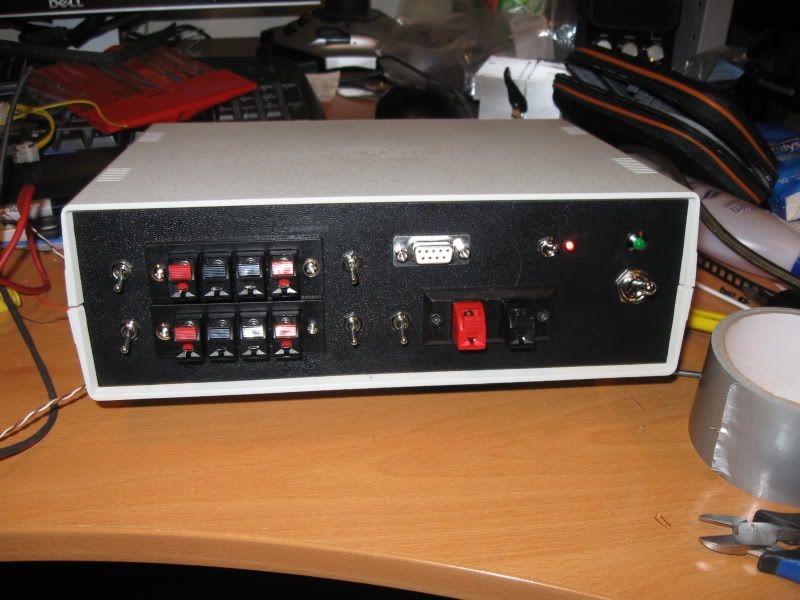
Very nicely done, are they all 12V rails or are any of them 5V? I particularly like those separate switches, so you can safely connect/disconnect when in use. Whats the difference between the 4 smalls and the 1 big? Also what is the Sub-D9 connected to, do you have a board in there as well?
Neat! Yes, 24W is quite a lot of power for a resistor to dissipate! You can get resistors mounted in a heatsink that you can bolt to a metal chassis = but as you are using a plastic case, that isn't possible.
Not sure what to suggest for that...
(\__/)
(='.'=)
(")_(")
Been helped or just 'Like' a post? Use the Thanks button!
My broadband speed - 750 Meganibbles/minute
The two rows of connections supply 12V1, -12V, 5V and 3.3V, black is ground. The larger connection supplies 12V2 and the D-sub, 12V, 5V, 3.3V & ground. The latter connection is there for devices which don't like power loss if the cable is accidentally yanked out, e.g. hard drives.
There are several sites that explain the conversion from ATX PSU into a bench supply. The one that I read (but now can't find) suggested joining all bar 1 of the 12V wires together. They are normally all fed by a single regulator circuit anyway, it is only the over current protection that then gives the "seperate" rails. The one seperate wire can then be connected to a resistor to provide the minimum load. You don't need to provide the min load to each "rail".
There are currently 1 users browsing this thread. (0 members and 1 guests)
 Posting Permissions

 Reply With Quote
