LinkBack URL
 About LinkBacks

This is a mod build I did nearly 2 years ago, it was only on modbrothers, but as that's now gone down I'm going to try to rebuild it here.
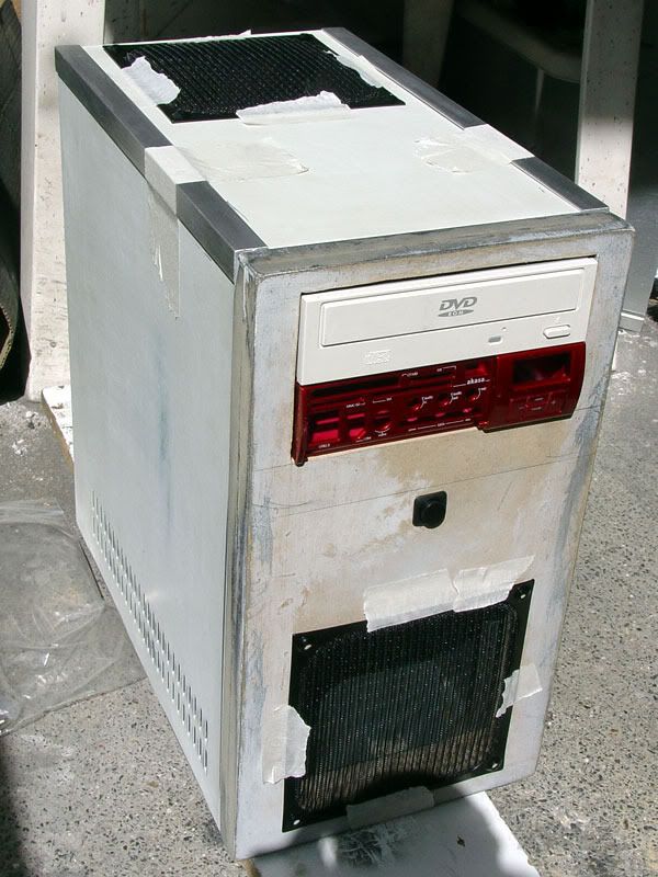
Yes the case is finished, it came out great and is still working well.
Following on from my original design work (I'll post it if I can recover it)
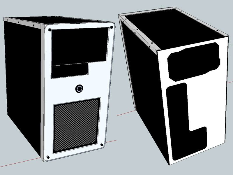
Yes I've finally come up with a name for it.The division of two opposites that form a whole, I think it's an ideal name for a black and white colour scheme build.
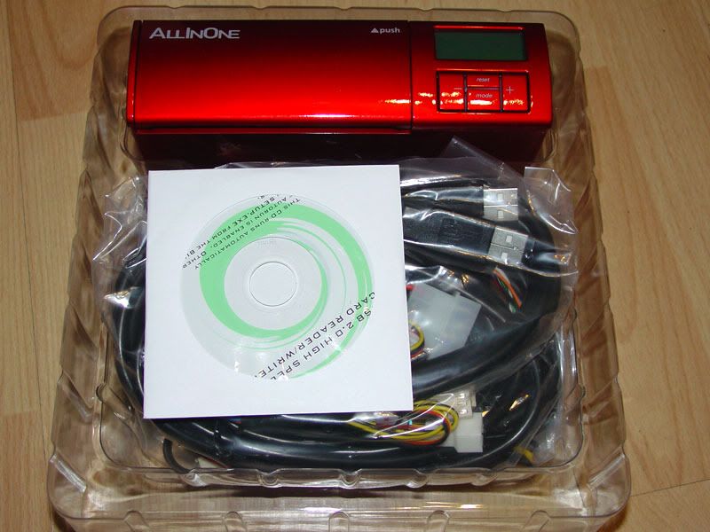
I was asked to build a pc by a lady at work, max budget £350, complete system.
Yes yet again I'm working to a very tight budget :? one of these days someone with a load of money will ask me to put a pc together, that or I'll win the lottery.
Well I could of just bought some cheap case to put it in, but where's the fun in that? This is a good excuse to practise my modding and she'll get a one of a kind case.
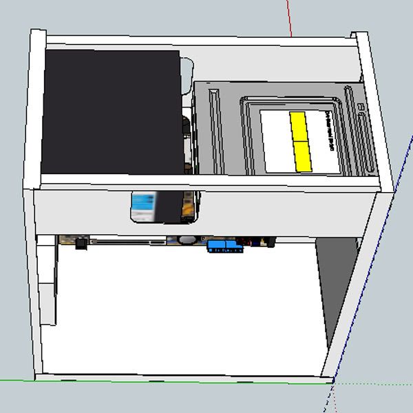
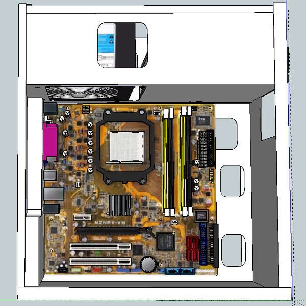
I've been bargain hunting and trolling 2nd hand sources for components, all the hard ware has cost about £290, leaveing me with £60 for the case, again could get a decent case for that, but again that's no fun.
Now to help shave off the costs (this was before I managed to get all the hardware) I picked up a couple of old chieftech mini-tower cases from work for nothing (I diverted them from their journey to the skip)
They are great little case, and I mean little, smaller than most mATX cases and very solid construction, I've happily stood on these cases before with out doing any damage to them.
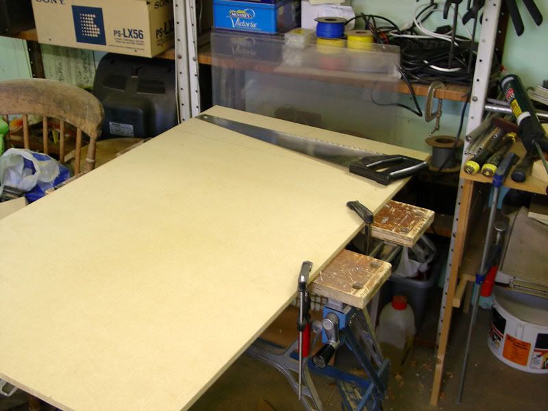
Here it is, a lovely beige canvas (sorry these where taken with my phone, so not the best of photos)
That's a 30cm/12inch ruler and a 140mm wire mesh filter on the top, gives you an idea of the size.
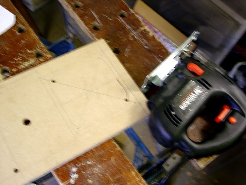
I've been working on this case on and off for a couple of weeks so there's a load more to come, however right now it's late and I need to go to sleep.
So here's the plan:
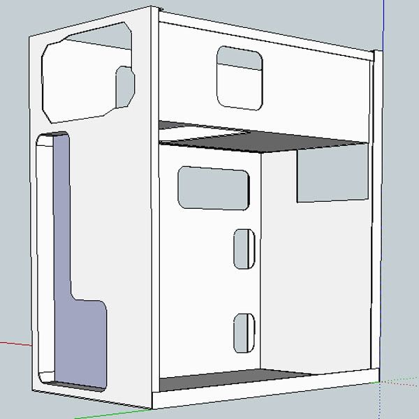
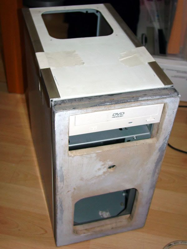
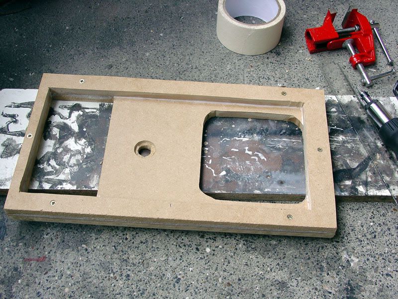
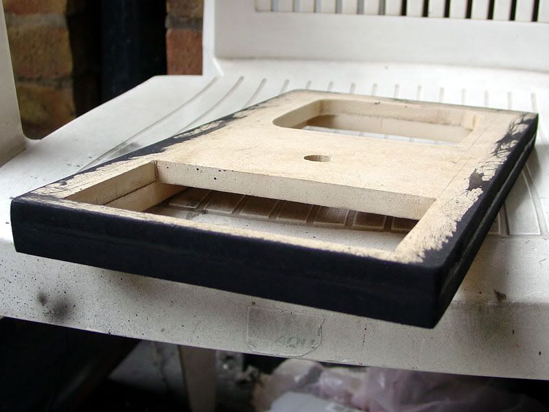
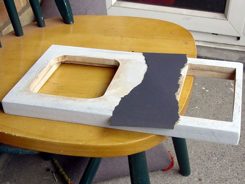
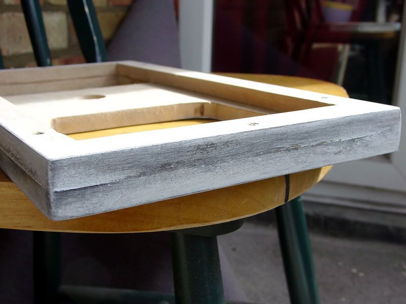
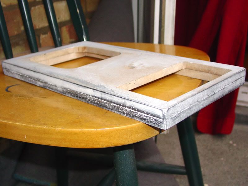
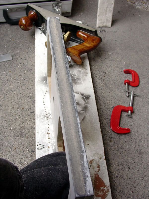
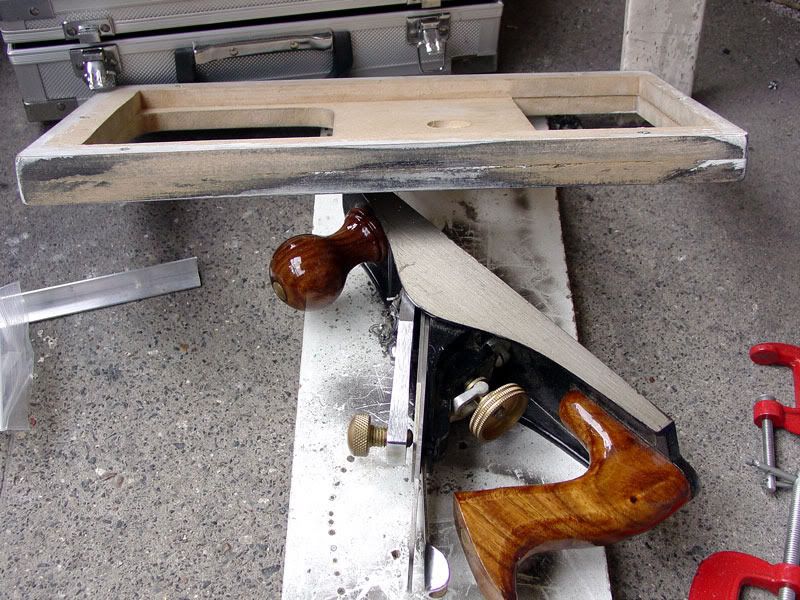
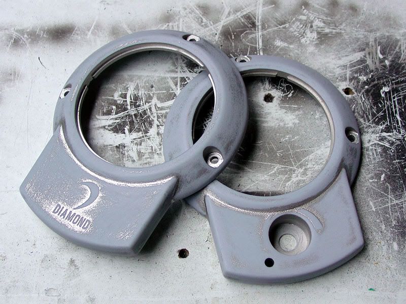
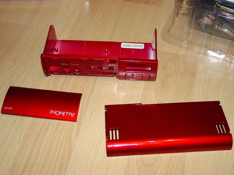
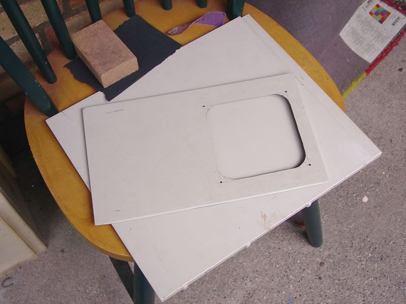
Throw away the front bezel, it's badly yellowed and rather ugly, build a whole new front bezel, I want something simple and elegant.
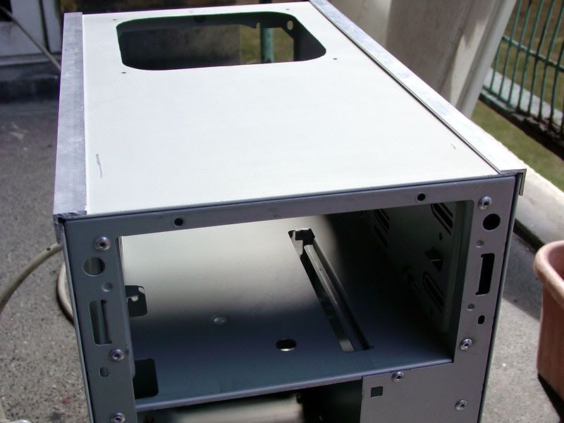
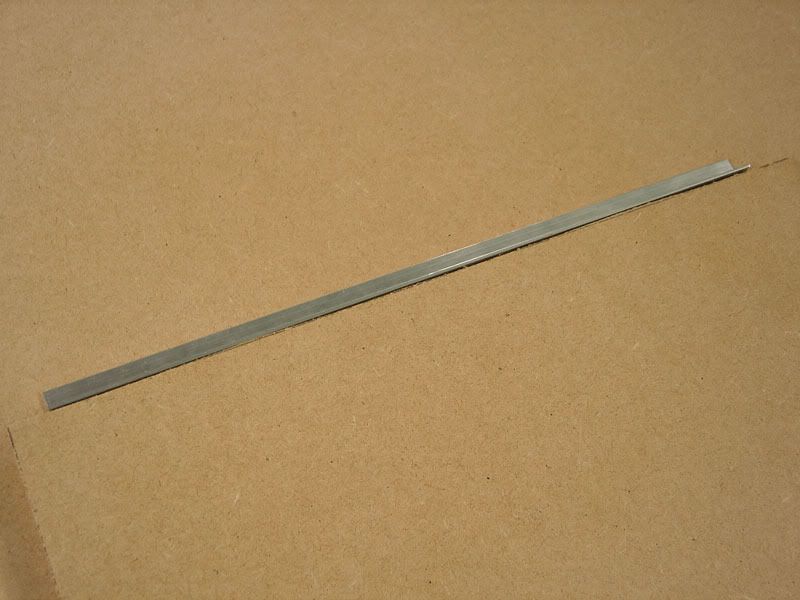
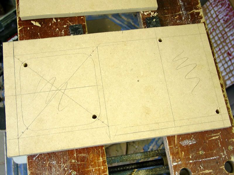
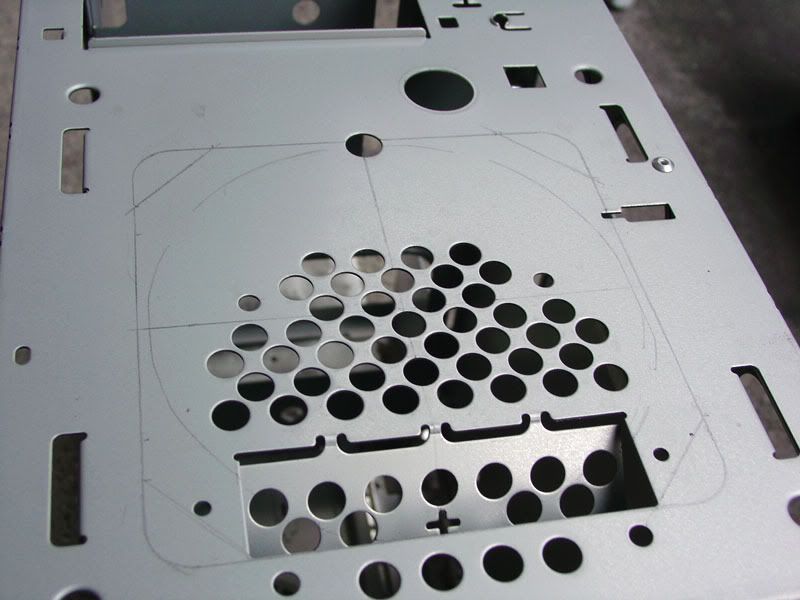
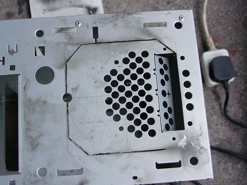
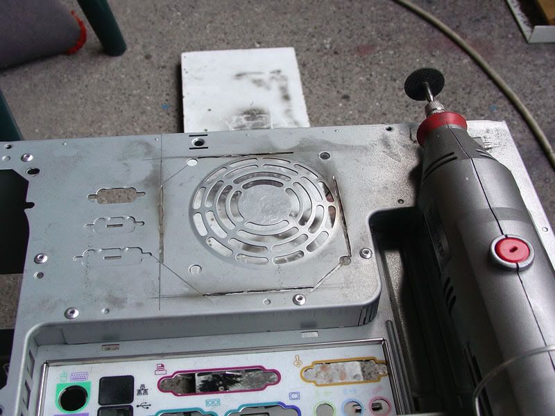
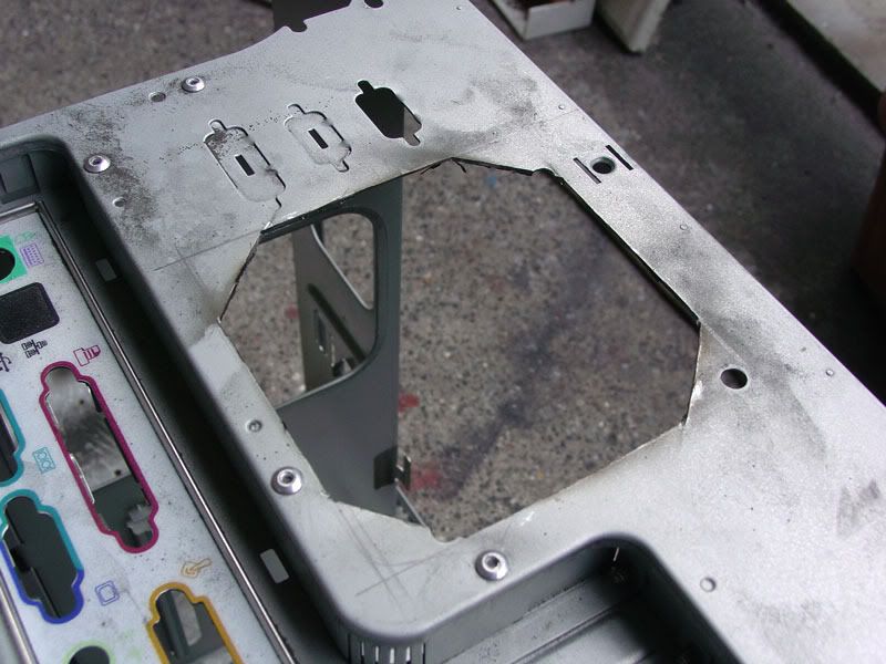
Cut holes for new fans, 120mm front & 92mm rear (couldn't fit a 120mm in the rear slightly too narrow)
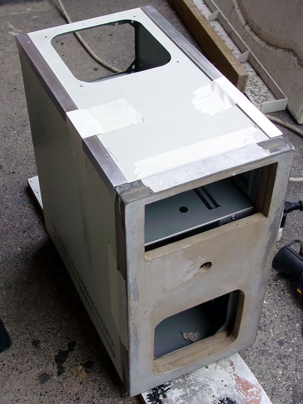
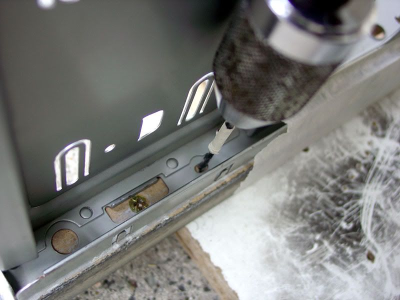
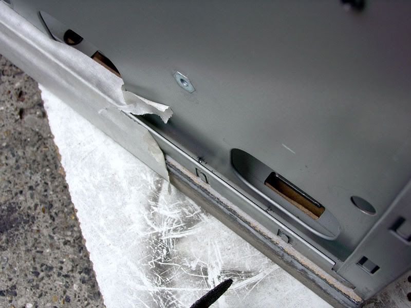
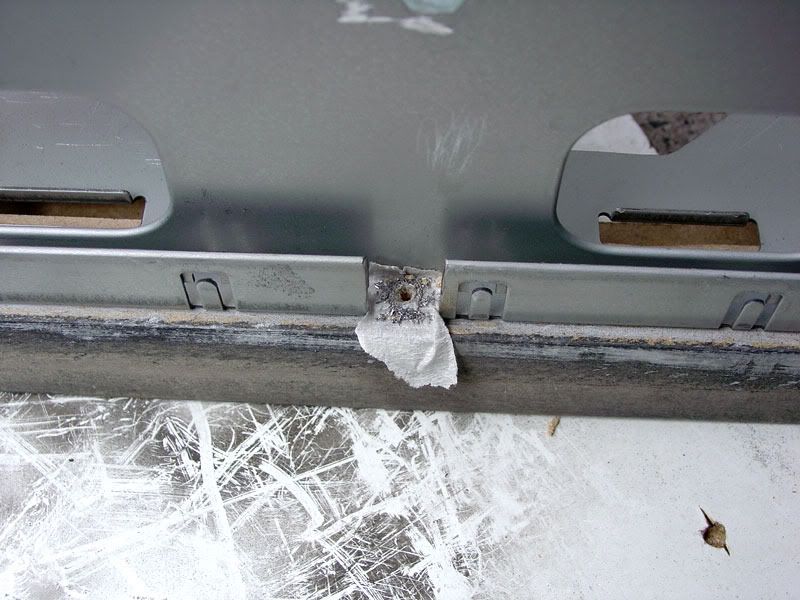
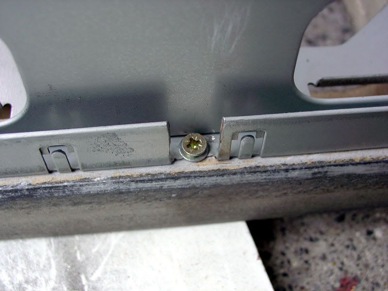
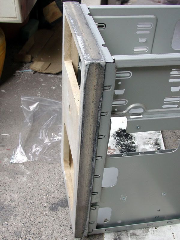
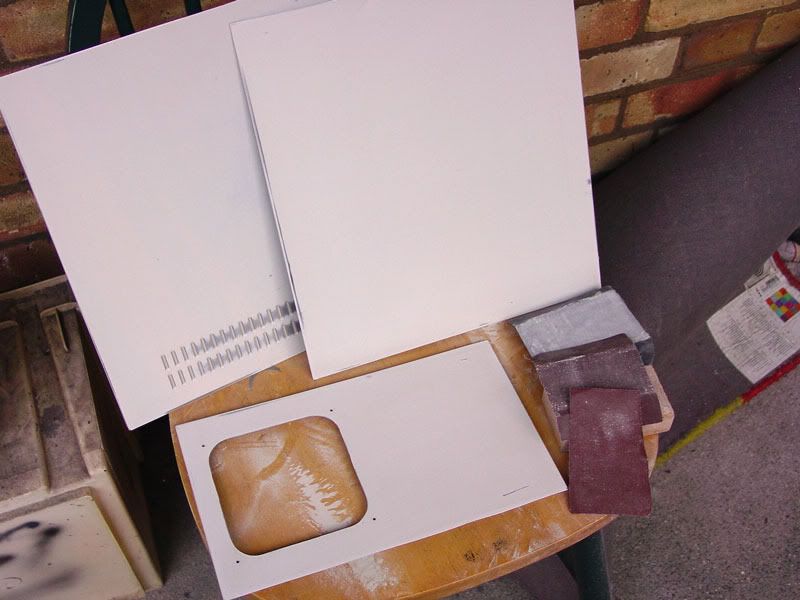
Convert the single piece U shaped side&top panel into 3 separate panels.
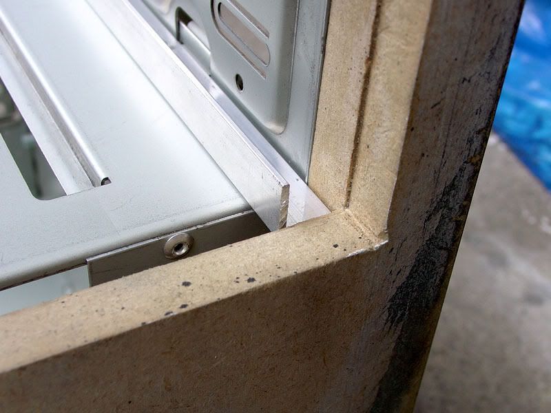
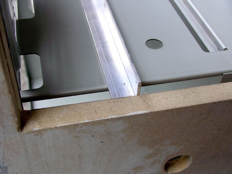
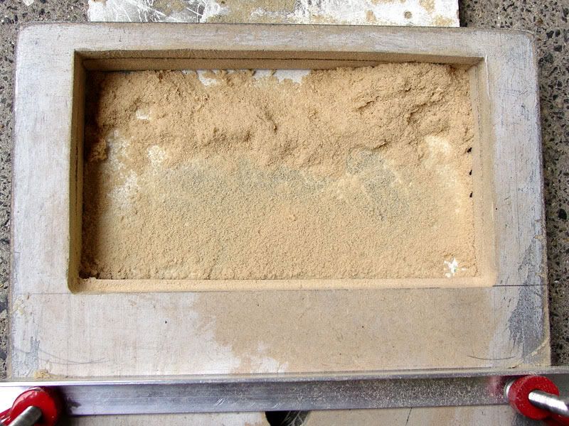
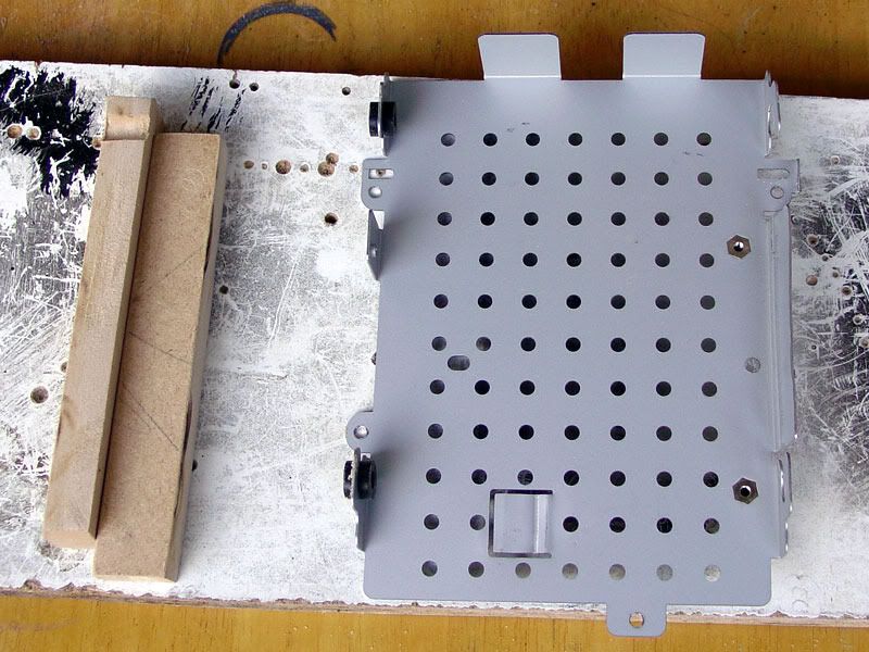
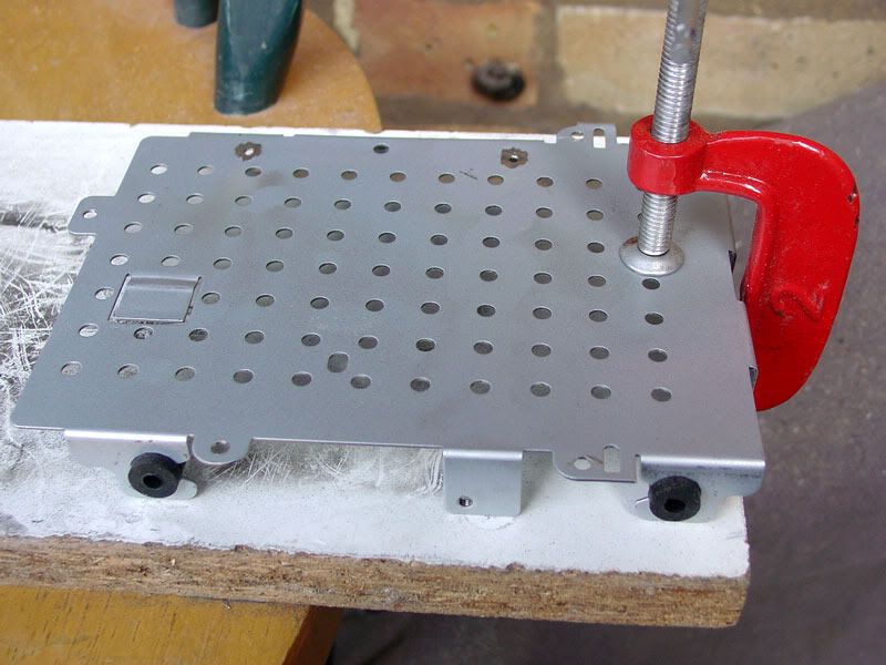
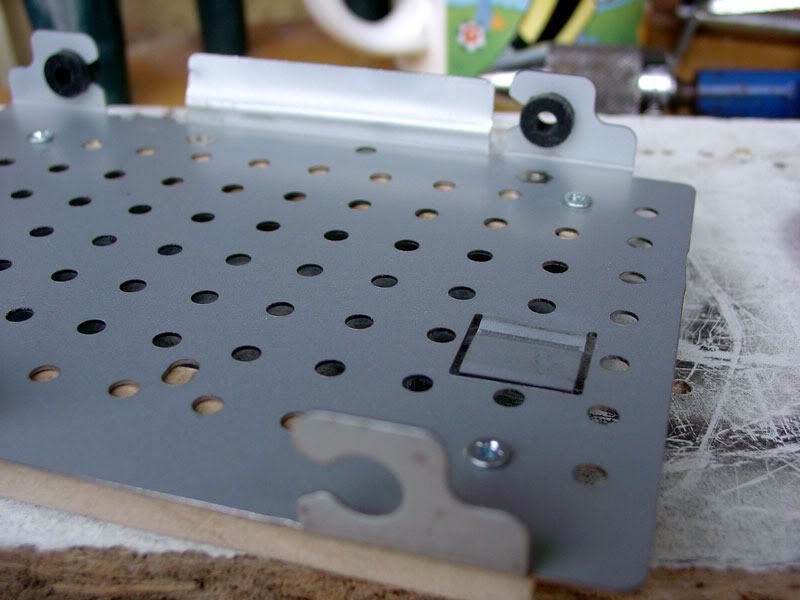
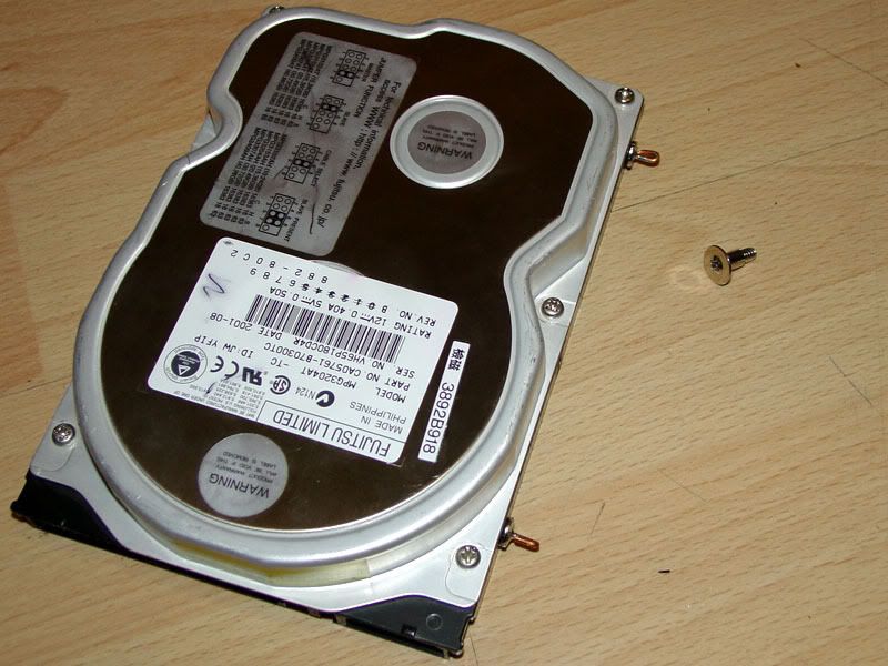
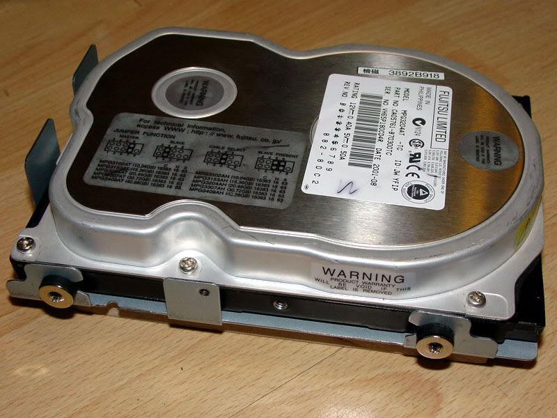
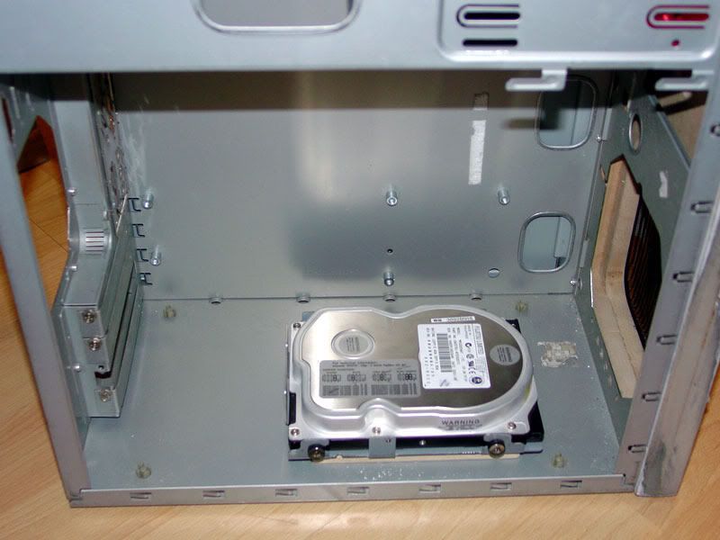
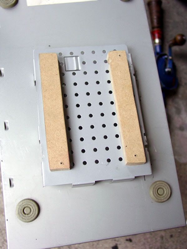
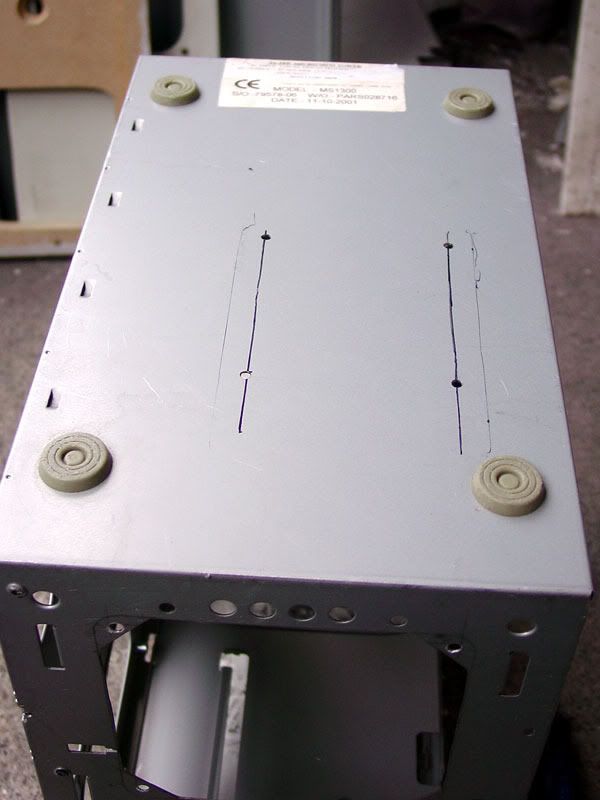
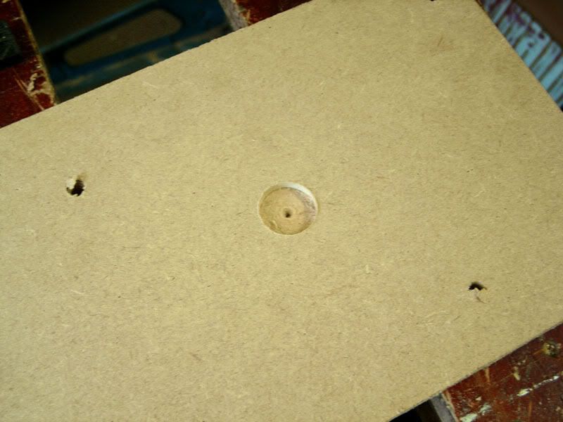
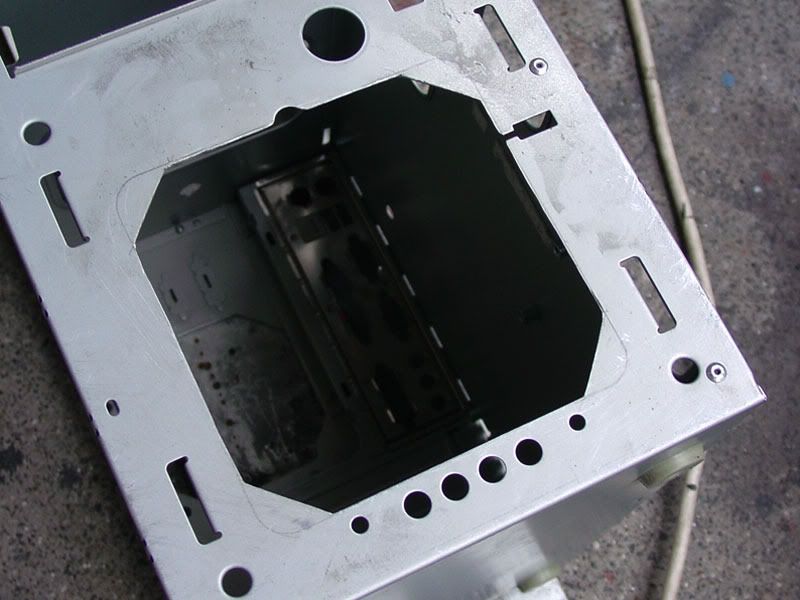
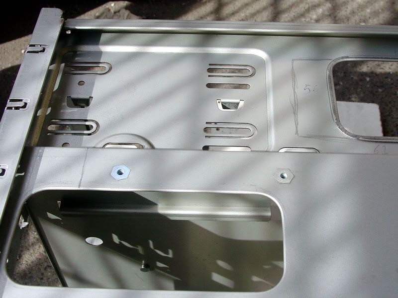
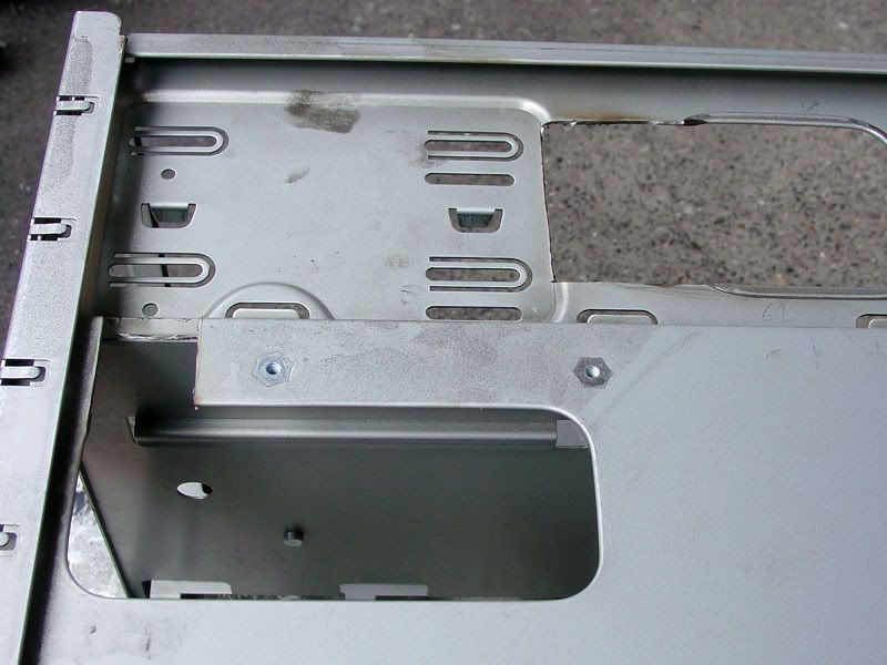
New hard drive mounting.
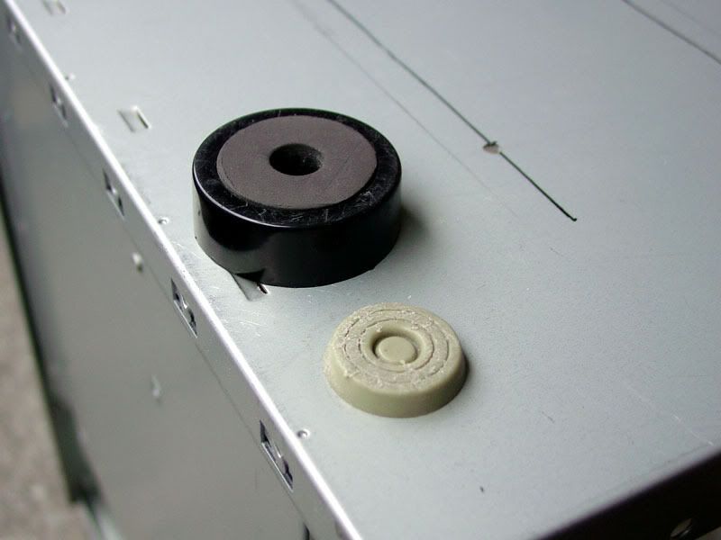
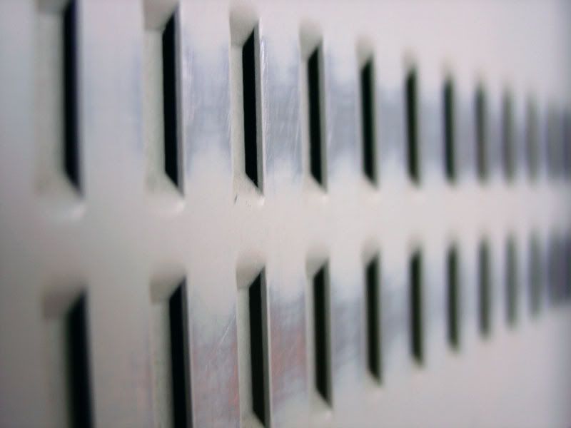
Add air filters
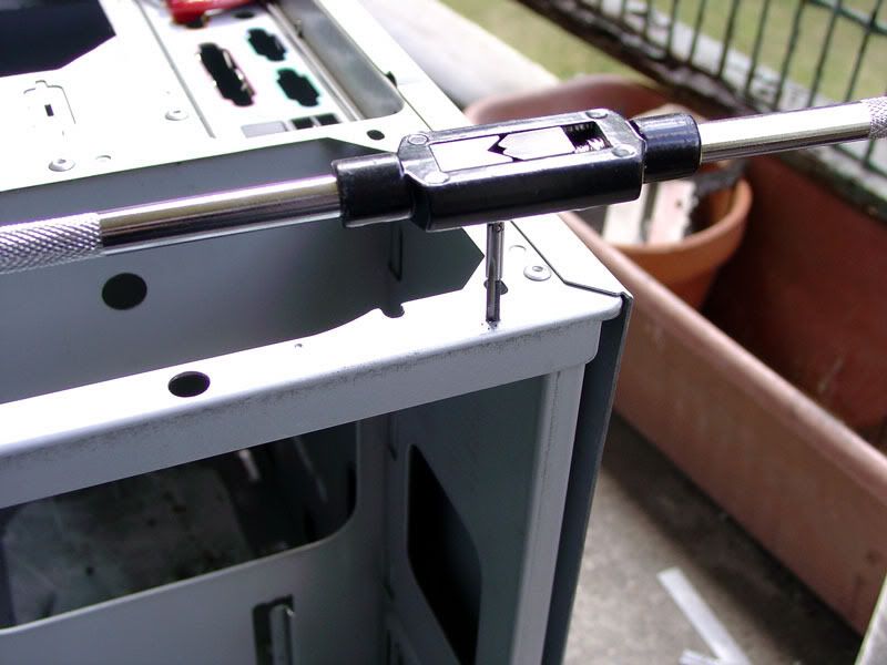
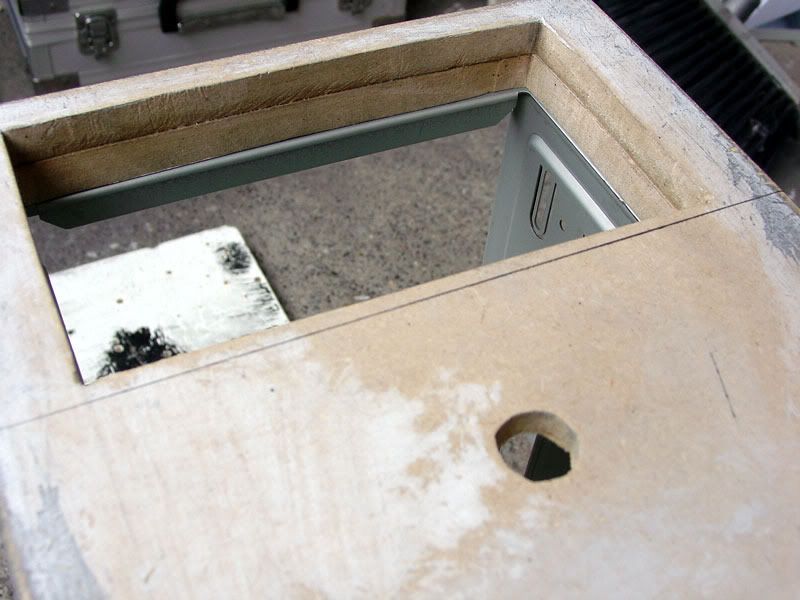
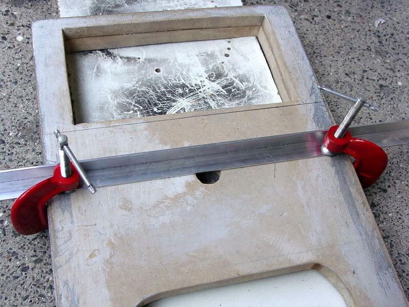
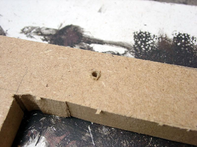
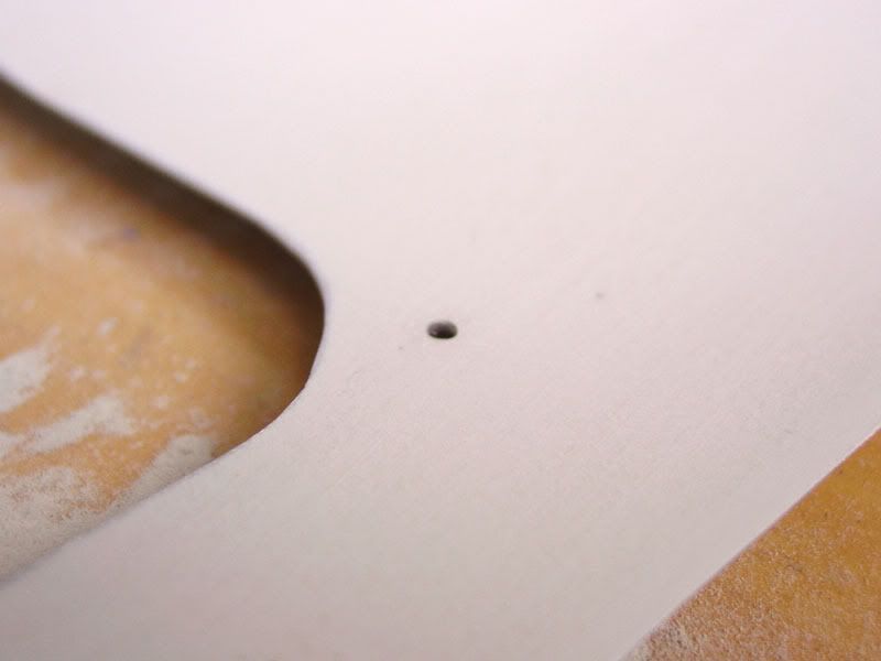
Cut additional cable management holes
Repaint, colour scheme is glossy white with black accents.
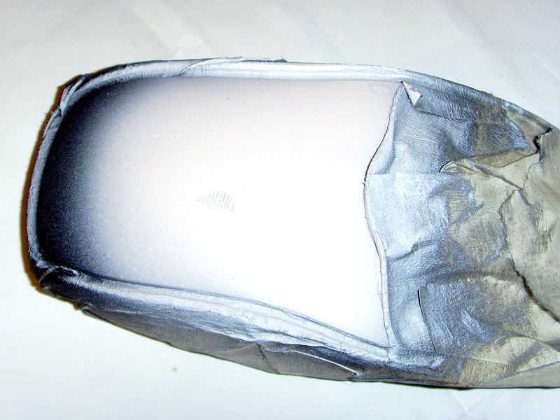
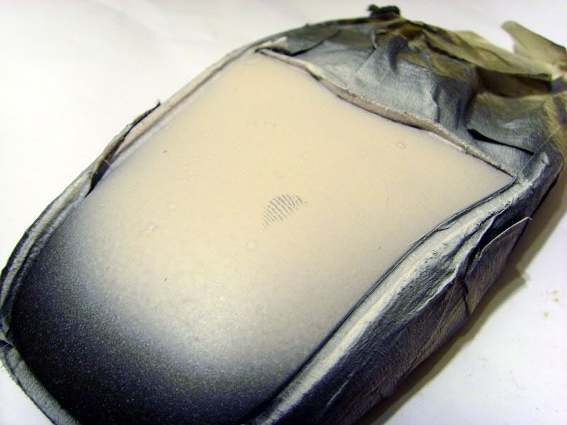
Colour match keyboard, mouse, speakers and monitor
Stay within budget!
Don't make a total pigs ear of it!
More to come soon.


 Reply With Quote
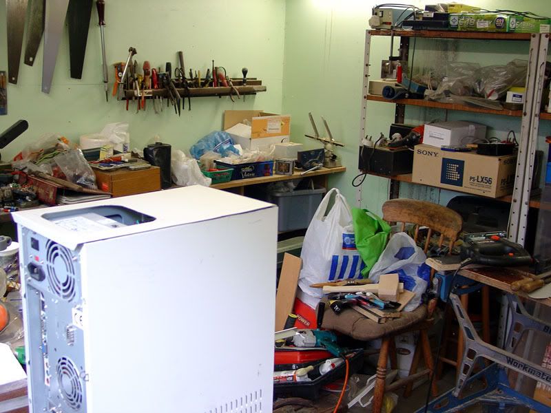


 me off
 I'll try and describe it.
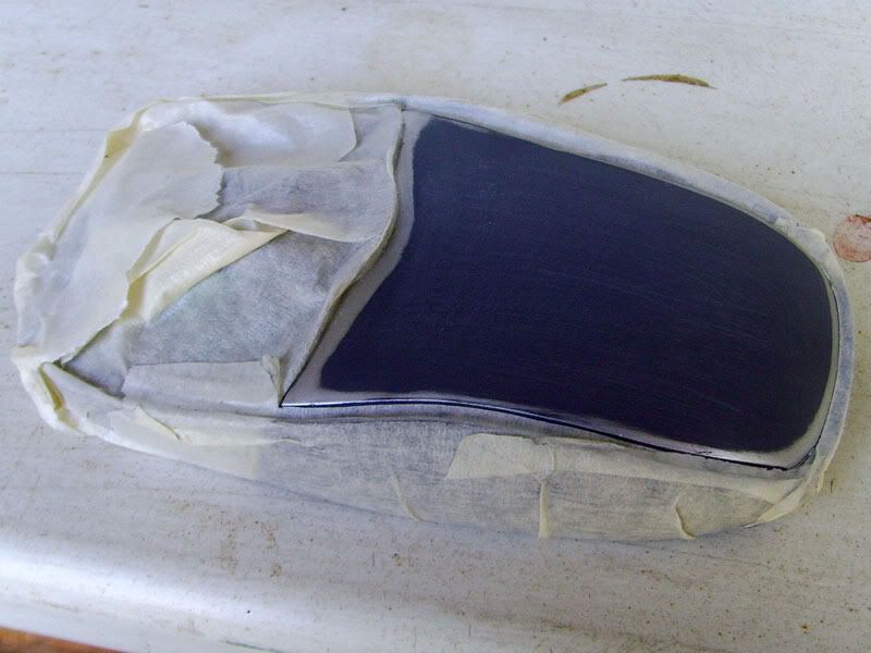


 Ok ok I'm sorry, I'll try to sort it out tonight.